
Center Dimension
Other Related Resources
Parent page: PCB Dialogs
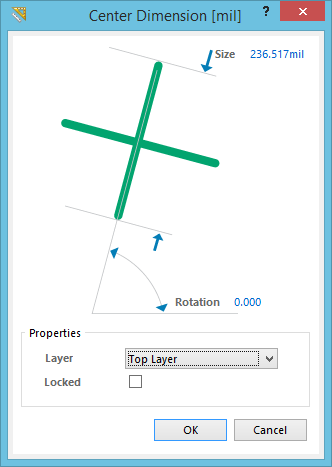
The Center Dimension dialog.
Summary
This dialog allows the designer to specify the properties of a Center Dimension object. A center dimension is a group design object. It allows for the center of an arc or circle to be marked.
Access
The Center Dimension dialog can be accessed during placement by pressing the Tab key.
After placement, the dialog can be accessed in one of the following ways:
- Double-clicking on the placed center dimension object.
- Placing the cursor over the center dimension object, right-clicking and choosing Properties from the context menu.
Options/Controls
- Size - the current length of the dimension's crosshair lines.
- Rotation - the angle of alignment of the dimension, measured anti-clockwise in degrees from the horizontal.
Properties
- Layer - the layer the dimension is currently assigned to. Dimensions can be assigned to any available layer, click on the list to view and select a different layer, from all those currently defined for the board.
- Locked - enable this option to protect the dimension from being edited graphically.