
Schematic - General
Contents
Parent page: Schematic Preferences
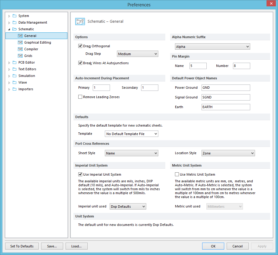
The Schematic - General page of the Preferences dialog.
Summary
The Schematic – General page of the Preferences dialog provides controls to configure the basic setup of schematic-based documents and the Schematic Editor workspace.
Access
The Schematic – General page is part of the main Preferences dialog (File | ![]() ) and is accessed by clicking the General entry under the Schematic folder, in the left hand pane of the dialog.
) and is accessed by clicking the General entry under the Schematic folder, in the left hand pane of the dialog.
Options/Controls
Options
- Drag Orthogonal - When dragging components with this option enabled, any wiring that is dragged with the component is kept orthogonal (that is, corners at 90°). If this option is disabled, wiring dragged with a component will be repositioned obliquely.
- Drag Step - Determines the distance between the steps created when dragging an object with parallel connection lines, over the range of
SmallesttoLarge.
- Drag Step - Determines the distance between the steps created when dragging an object with parallel connection lines, over the range of
- Break Wires At Autojunctions - with this option enabled, an existing wire (or bus, or signal harness) segment will be broken into two at the point where an autojunction is inserted. For example, when making a T-Junction, the perpendicular segment will be broken into two segments, one each side of the junction. With this option disabled, the segment will remain unbroken at the junction.
Alpha Numeric Suffix
Multi-part components can use either a Numeric or Alpha part identifier suffix (for example, U1:1 or U1A). Select the preferred style from the drop-down list.
- Alpha - Select this option to use an alpha component suffix -
U1A, U1B,etc. - Numeric, separated by a dot - Select this option to use an numeric component suffix with dot separator -
U1.1, U1.2,etc. - Numeric, separated by a colon - Select this option to use an numeric component suffix with colon separator -
U1:1, U1:2,etc.
Pin Margin
- Name - Normally, component pin names are displayed inside the body of the component, adjacent to the corresponding pin. This option controls the placement of component pin names. It specifies the distance from the component outline to the start of the pin name text.
- Number - Normally, component pin numbers are displayed outside the body of the component, directly above the corresponding pin line. This option controls the placement of the pin numbers. It specifies the distance from the component outline to the start of the pin number text.
Auto-Increment During Placement
- Primary - Enter a value to auto-increment component pin designators as pins are sequentially placed for a component. With the value set to 1 for example, the designators of a sequence of placed pins would be
1, 2, 3,etc. Note that the designator of the first pin would be set to1in the Pin Properties dialog as the pin is placed. - Secondary - Enter a value to auto-increment component pin names as pins are sequentially placed for a component. With the value set to 1 for example, the designators of a sequence of placed pins would be
D1, D2, D3,etc. Note that the name of the first pin would be set toD1in the Pin Properties dialog as the pin is placed. If set to-1,the pin name would decrement –D8, D7, D6,etc. - Remove Leading Zero - Enable this option to remove leading zeros from the string of numbers. For example if it was
002and the option is enabled, the leading zeros would be removed for a result of2.
Default Power Object Names
- Power Ground - When placing a Power Ground style power port in a schematic, its net name will default to this value. If the field is empty, then the last valid value will apply to any new ports of this style. The default name is
GND. - Signal Ground - When placing a Signal Ground style power port in a schematic, its net name will default to this value. If the field is empty, then the last valid value will apply to any new ports of this style. The default name is
SGND. - Earth - When placing an Earth power port in a schematic, its net name will default to this value. If the field is empty, then the last valid value will apply to any new ports of this style. The default name is
EARTH.
Defaults
- Template - Use this field to set the default template file that will be used to create new schematic sheets. Choose from the drop-down menu list of predefined templates based on standard page sizes. To not use a template, simply set the field to No Default Template File.
Port Cross References
- Sheet Style - Choose one of the following sheet styles for the cross referencing of ports on a schematic sheet or schematic sheets within a project.
- None: No sheet style is added in the cross reference string of all ports.
- Name: Names of the sheets that the ports are linked to are added in the cross reference strings.
- Number: The sheet numbers of the sheets that the ports are linked to are added in the cross reference strings.
- Location Style - Choose one of the following location styles for the cross referencing of ports on a schematic sheet or schematic sheets within a project.
- None: No location style is added in the cross reference string of all ports.
- Zone: The reference zone numbering (the sheet borders have the zones) is added in the cross reference strings of all ports that are associated to the parent objects, such as the location of sheet symbols.
-
Location X,Y : The locations of the ports are published in brackets in the cross reference strings for all ports that are associated to the parent objects, such as the location of sheet symbols. Note, the design project needs to be compiled first before any cross references can be added to the ports.
Imperial Unit System
- Use Imperial Unit System - Enable this option to use imperial units in schematic projects.
- Imperial Unit used - From the drop-down list, choose one of the available imperial units; mils, inches, DXP default units (10 mils) and Auto-Imperial. If Auto-Imperial is selected, the system will switch from
milstoincheswhen the value is greater than 500 mils.
Metric Unit System
- Use Metric Unit System - Enable this option to use the metric units for schematic projects.
- Metric Unit used - From the drop-down list, choose one of the available metric units; millimeters,centimeters, meters, Auto-Metric. If the Auto-Metric is selected, the system will switch from
mmtocmwhen the value is greater than 100 cm.
Unit System
Reports the current default unit setting for new documents, and indicates a pending unit change.