Image
Contents
Parent page: Schematic Objects

A placed Image.
Summary
An image object is a non-electrical drawing primitive. It is essentially a container for an image file that can be imported and placed onto a schematic sheet. The image associated with an image object can either be linked or embedded.
Availability
Image objects are available for placement in both Schematic and Schematic Library Editors:
- Schematic Editor - click Home | Graphical Elements |
 from the main menus.
 - Schematic Library Editor - click Home | Place | from the main menus.
Placement
After launching the command, the cursor will change to a cross-hair and you will enter image placement mode. Placement is made by performing the following sequence of actions:
- Position the cursor and click or press Enter to anchor the first corner of the image's frame, in which the image itself will reside.
- Move the cursor to adjust the size of the frame and click or press Enter to complete frame placement.
- The Open dialog will appear, from where you can browse to and select the required image. Select the file you wish to insert and press the Open button to complete image placement.
- Continue placing further image objects, or right-click or press Esc to exit placement mode.
Additional actions that can be performed during placement – while the image's frame is still floating on the cursor, and before its first corner is anchored – are:
- Press the Tab key to access an associated properties dialog, from where properties for the image can be changed on-the-fly.
- Press the Alt key to constrain the direction of movement to the horizontal or vertical axis, depending on the initial direction of movement.
- Press the Spacebar to rotate the image frame anti-clockwise or Shift+Spacebar for clockwise rotation. Rotation is in steps of 90°.
- Press the X or Y keys to mirror the image frame along the X-axis or Y-axis respectively.
Graphical Editing
This method of editing allows you to select a placed image object directly in the workspace and change its size, shape or location, graphically.
When an image object is selected, the following editing handles are available:
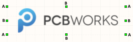
A selected Image.
- Click and drag A to resize the image frame in the vertical and horizontal directions simultaneously.
- Click and drag B to resize the image frame in the vertical and horizontal directions separately (provided the X:Y Ratio 1:1 option in the Graphic dialog is disabled).
- Click anywhere on the image – away from editing handles – and drag to reposition it. While dragging, the image can be rotated (Spacebar/Shift+Spacebar) or mirrored (X or Y keys to mirror along the X-axis or Y-axis respectively).
Non-Graphical Editing
The following methods of non-graphical editing are available:
Via an Associated Properties Dialog
Dialog page: Graphic
This method of editing uses the Graphic dialog to modify the properties of an image object.
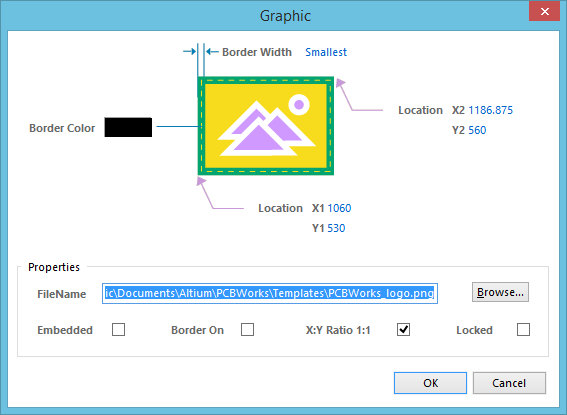
The Graphic dialog.
The dialog can be accessed during placement by pressing the Tab key.
After placement, the dialog can be accessed in one of the following ways:
- Double-clicking on the placed image object.
- Placing the cursor over the image object, right-clicking and choosing Properties from the context menu.
Via an Inspector Panel
Panel pages: SCH Inspector, SCHLIB Inspector
An Inspector panel enables the designer to interrogate and edit the properties of one or more design objects in the active document. Used in conjunction with the Find Similar Objects dialog, the panel can be used to make changes to multiple objects of the same kind, from one convenient location.
Using Vector Graphics
The majority of supported image formats - including bmp, png, jpg, and tiff - are Raster-based. Simply put, they are created (or composed) graphically, of a fixed series of dots. And while all of these image formats render adequately, their attraction diminishes when the image is scaled. Zoom right in to an image in one of these formats and the 'blocky' or 'pixelated' nature of the image's dot composition soon becomes apparent. The solution to this, is to use a Vector-based image format. Vector images are composed of graphical shapes rather than dots, which are preserved upon scaling.
The Schematic Editor supports vector-based graphics in the form of WMF (Windows Meta File) and SVG (Scalable Vector Graphics) formats.

An example image on a schematic. A PNG version above, with its SVG incarnation below. When zoomed-in, the quality of the latter becomes appreciatively noticeable.
Notes
- The following image formats are supported:
.bmp,.dcx,.dib, .emf,.jpg,.pcx,.png,.rle,.tif, .svg,.tga,.wmf. - To retain the image's original aspect ratio, ensure that the X:Y Ratio 1:1 option is enabled in the Graphic dialog. When this option is enabled, the image will be scaled to fit optimally into the frame size specified while maintaining the original aspect ratio of the image. If the option is disabled, the image is stretched to fit exactly into the drawn frame size.
- A copy of a placed image will only be stored inside the schematic sheet if the corresponding Embedded option is enabled in the Graphic dialog. If this option is disabled, only a link to the image file will be stored. Care should be taken when using linked images – if the location of the image changes, you will need to update the link accordingly, using the FileName field in the Graphic dialog.