Collaborating between PCBWorks and SOLIDWORKS
Contents
- How the Applications Collaborate
- Collaboration Panels
- Component Requirements
- Where are my Components?
- Board Shape Requirements
- Support for SOLIDWORKS Slot, Spline, Ellipse and Parabolic Shapes
- Starting the Collaboration Process in PCBWorks
- Starting the Collaboration Process in SOLIDWORKS
- Examining and Accepting Changes
Today's sophisticated electronic products come in all manner of unusual shapes and sizes - designing these products demands close collaboration between the mechanical and electronic design teams throughout the development process.
PCBWorks can help with this, allowing the ecad and mcad designers to directly pass design changes back and forth between PCBWorks and SOLIDWORKS®. Make a change to the board shape or the positioning of a critical component in PCBWorks, then click a button to pass those changes across to your fellow designer in SOLIDWORKS.
Underlying these collaboration capabilities is an ECAD-MCAD Project Collaboration Server (or Altium Vault). As well as providing secure storage for the ecad design, it also acts as the conduit between the design spaces, transferring changes to the board shape and components, as well as the designers' comments.
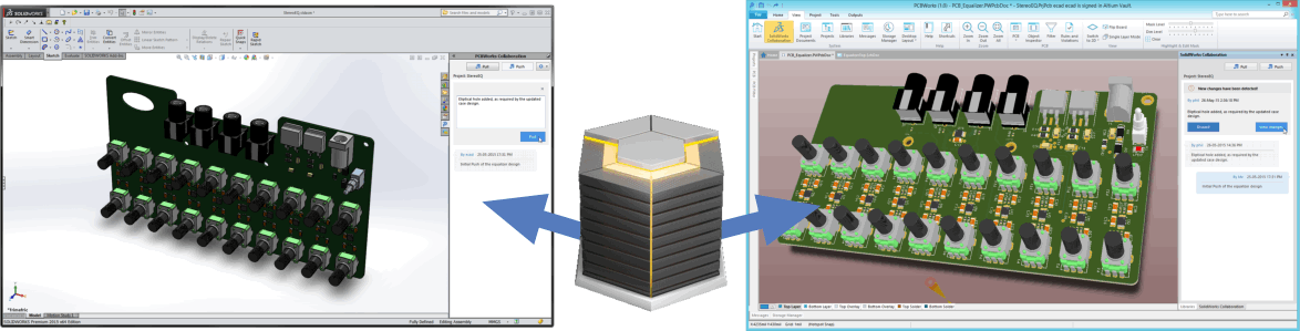
Design changes are passed between SOLIDWORKS and PCBWorks transparently through the Collaboration Server/Vault.
How the Applications Collaborate
SOLIDWORKS and PCBWorks collaborate with each other through an ECAD-MCAD Project Collaboration Server (or Altium Vault), whose behind-the-scenes role is quite transparent. The designer working in each application uses a Collaboration panel to Push and Pull design changes from one space to the other. Notifications about incoming changes appear automatically in the Collaboration panel, as soon as a Push is performed on the other side.
Collaboration Panels
To display the Collaboration panel:
- PCBWorks - click the View | System |
 button on the ribbon.
 - SOLIDWORKS - select the Task Pane tab from the set of tabs down the right of the application.
Each application has a Collaboration panel, through which local changes are either Pushed into the Collaboration Server/Vault, or Pulled from the Collaboration Server/Vault.
Component Requirements
3D component models can be passed back and forth during collaboration.
On the PCBWorks side, the model must be part of the component (placed in the PCB Library editor). Free 3D models placed directly on the PCB are not supported.
The following 3D model formats are supported:
- PCBWorks 3D Body Objects
- SOLIDWORKS parts - *.SldPrt (up to 2015 format)
- Parasolid Models - *.x_t and *.x_b (up to V27)
- STEP models - *.Stp and *.Step (203 & 214 formats)
At this stage, parts cannot be placed in SOLIDWORKS and pushed across to PCBWorks.
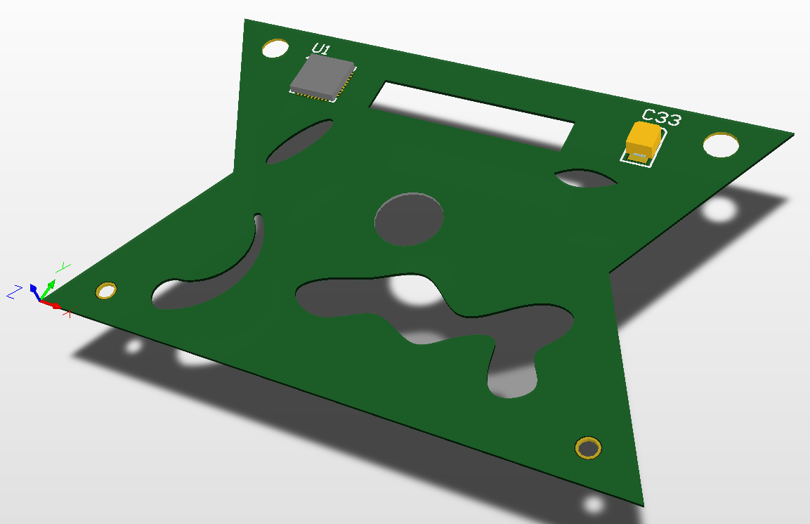
Board Shape Requirements
Any shape defined in PCBWorks will transfer correctly to SOLIDWORKS. While there is strong support for SOLIDWORKS shapes, not all are fully supported, as described below.
Starting the Collaboration Process in PCBWorks
In PCBWorks, each project is created and stored as a managed project, in an ECAD-MCAD Project Collaboration Server (or Altium Vault).
To commence collaboration from PCBWorks:
- The schematic design is developed in the usual manner.
- Add a PCB to the project, and save the project. You can commence the collaboration process now using the blank board, or if you prefer, you can transfer the components from the schematic to the board first, in the usual manner (Design » Update PCB Document <PcbFilename>).
- Save All modifed files (Files menu).
- Select Home | Project | Project » Commit Project to commit all changes into the Collaboration Server/Vault.
- Make the PCB the active document in PCBWorks.
- In the SOLIDWORKS Collaboration panel, click the Push button. You will be prompted to enter a comment, do this, then click the Post button to complete the process, as shown in the images below. This action will:
- Create a Parasolid model file for the board and each component in the design, and store them in the
\<ProjectName> SOLIDWORKS Collaboration\Exported 3D Models\folder in the working copy of the ecad project folder. - Release these models to the
\Mechatronic 3D Models\folder in the Collaboration Server/Vault.
- Create a Parasolid model file for the board and each component in the design, and store them in the
The steps to collaborating from PCBWorks - click Push in the Collaboration panel, then Post a message to upload the shared elements (board shape and components).
To then access this project from SOLIDWORKS:
- In SOLIDWORKS, click the icon to open the PCBWorks Collaboration panel.
- Click the Create from Repository button. The Select Project dialog will open, listing all of the managed projects in the Collaboration Server/Vault, that the current SOLIDWORKS user has permission to open.
- Select the project from the list of managed projects, and click OK. Here you are letting SOLIDWORKS know which managed project you want to open the board from, this step will fail if the board has not been Commited in PCBWorks.
- The next step is to save the SOLIDWORKS assembly that will hold the board design on the SOLIDWORKS side. The Save As dialog will appear, configure this to save the SOLIDWORKS assembly in a suitable location.
- The Altium SOLIDWORKS Collaboration dialog will then appear, showing the status of the various steps of the process: such as Pulling Design from Server... Applying Component Change..., and so on. This process will:
- Read the board shape from the the Collaboration Server/Vault and create a SOLIDWORKS assembly of it (
*.sldsam), - Download the Parasolid component models into the
\Temperature Sensor Electronic Parts\Downloaded Models\mcad folder, - Create a SOLIDWORKS component (
*.sldprt) from each of the Parasolid component models, - Position the components on the board.
- Read the board shape from the the Collaboration Server/Vault and create a SOLIDWORKS assembly of it (
- You can now reshape the board and move the components in SOLIDWORKS, Push those changes back into the Collaboration Server/Vault, and then Pull the updated PCB design into PCBWorks.
Starting the Collaboration Process in SOLIDWORKS
The workflow can also commence in SOLIDWORKS and then move to PCBWorks if required.
The approach to working in this direction is:
- In SOLIDWORKS, click the icon in the set of panel icons on the right of SOLIDWORKS to open the PCBWorks Collaboration panel.
- Click the Create New Board Assembly button in the panel.
- The Select Project dialog will open, now you can either:
- create a board for an existing project by selecting the required managed project in the list, or
- click the Create New Project button to make a new managed project in the Collaboration Server/Vault. If you choose this option the Create New Server Project dialog will open, enter a suitable Name and Description for the project. The Repository setting is the repository used by the Collaboration Server/Vault to store managed projects, typically it will be set to the
DefaultRepository, click OK and the dialogs will close.
- The Save As dialog will then open - ready to name the SOLIDWORKS assembly. Select/enter a suitable location and name, then Save the assembly.
- You will be presented with a default board shape in SOLIDWORKS, edit the shape as required, save it, and return to the assembly editor (note that SOLIDWORKS runs as multiple applications, you can be in the part editor or the assembly editor).
- With the
*.sldasmas the active document in SOLIDWORKS, the PCBWorks Collaboration panel will show the Pull and Push buttons, click Push to push the design into the Collaboration Server/Vault.
You can now access this new board shape from PCBWorks:
- In PCBWorks, select File » Open Project, the Open Managed Project dialog will appear.
- Select the required managed project in the list and click OK to open the project.
- Next you need to add a blank PCB to the project, select Home |Project | Project » Add new PCB, the Enter File Name dialog will appear, name the new PCB and click OK to save it as part of the project - it will be opened, ready for editing.
- The next step will be to update this board based on the shape defined in SOLIDWORKS and Pushed to the Collaboration Server/Vault. It is easier to see the updates when the board is displayed in 3D mode, press the 3 shortcut to switch to 3D Display mode.
- If it is not visible, open the SOLIDWORKS Collaboration panel, it will detect that there is a board active and flag that New changes have been detected!
- Click the View Changes button, the panel will change to list all the changes detected, click on a change to view the change in the workspace, it will flash 3 times in purple.
- Enable the checkbox for the change(s) you wish to accept, and click the Accept button. The board shape / cutouts will change to match the proposed purple shape.
- Right-click on the board in the PCBWorks Projects panel and select Save.
- Right-click on the project in the Projects panel and select Save Project.
- Right-click on the project in the Projects panel and select Commit Project, this will save the project file and commit all changed files to the Collaboration Server/Vault.
Examining and Accepting Changes
Both PCBWorks and SOLIDWORKS present potential changes using a simple animation, flashing or animating a purple shape to represent the new object / location.
The animated GIF below shows an example of three component relocations being passed from SOLIDWORKS to PCBWorks. Click on a proposed change to animate it in the workspace, enable the Accept checkbox to update the design to include that change. Use the commands in the right-click menu to toggle the state of multiple checkboxes.
The objects that have changed are presented in purple, making it easy to identify the before and after states. Enable the Accept checkbox for each change you want to make.