Component Management in PCBWorks
Contents
Parent page: Exploring PCBWorks
A component is the general name given to a part that can be placed into an electronic design during the design capture process. In its common form, a component is generally composed of a logical symbol that is applied to the design’s schematic, and a footprint pattern (model) that will physically represent the component on the PCB. Components are ‘wired’ together to form the complete design.
The initial task in that design process is generally capturing its circuitry in a schematic, where a placed component provides a graphical symbol that includes the component’s electrical connection points defined by pins. In PCBWorks this schematic representation of the component also provides a range of optional properties, parameters and links to a PCB footprint pattern – or more correctly, a 2D and/or 3D model that physically represents the component on a PCB.
Schematic component definitions (composed of a symbol, model links, parameters etc) are collectively stored in a Schematic Library file (*.SchLib) that can be loaded in PCBWorks. PCB model definitions are similarly stored in a PCB Library (*.PcbLib), where its constituent models are linked to by the symbol (component) definitions in a Schematic Library.

The base Schematic component definition in a Schematic Library includes links to suitable PCB models in a PCB Library, satisfying both domains with a unified component.
This unified component format means that its schematic representation provides all the information required to implement a component in both the schematic and PCB design domains. When a schematic design is transferred to the PCB domain (through the Update PCB process), PCBWorks will locate and place the PCB model(s) defined by the schematic component’s model link(s).
Working with Sch/Pcb Libraries
In PCBWorks, individual Schematic and PCB library files can used in a several ways, depending on requirements :
- Library files can be added to a design project, where they will be available for use whenever the project is loaded.
- Libraries can be stored separately, and then installed in PCBWorks as permanently available libraries.
- Schematic and PCB library files can be added to a Library Package project, which can be compiled to create a single Sch/Pcb Integrated Library file – see below for more information.
In all cases the central point for accessing and installing Schematic and PCB libraries is via the Libraries panel – select View |System | Libraries. The panel provides a list of components (symbols/models) in the currently selected library, including a preview of the each component entry’s symbol and/or footprint.
When viewing an opened Schematic library, which contains the base information for a unified component, the Libraries panel displays a graphic summary of any linked PCB models.

The Libraries panel is command central for all common component and library management tasks.
Libraries can be added to the current project or installed through the Available Libraries dialog, accessed from the panel’s ![]() button. Libraries can also be installed in the Data Management – Installed Libraries page in the PCBWorks Preferences dialog (File »
button. Libraries can also be installed in the Data Management – Installed Libraries page in the PCBWorks Preferences dialog (File » ![]() ).
).
Editing components
Components contained in individual schematic and PCB libraries can be edited (or created/deleted) with the PCBWorks library editor and the associated SCH/PCB Library panels.
To open a schematic component for editing, right-click its entry in the Libraries panel list and select Edit Component from the context menu. Similarly, to edit a footprint in an opened PCB Library, select Edit Footprint from the Libraries panel right-click context menu. Note that a library can also be opened for editing directly from the Projects panel.
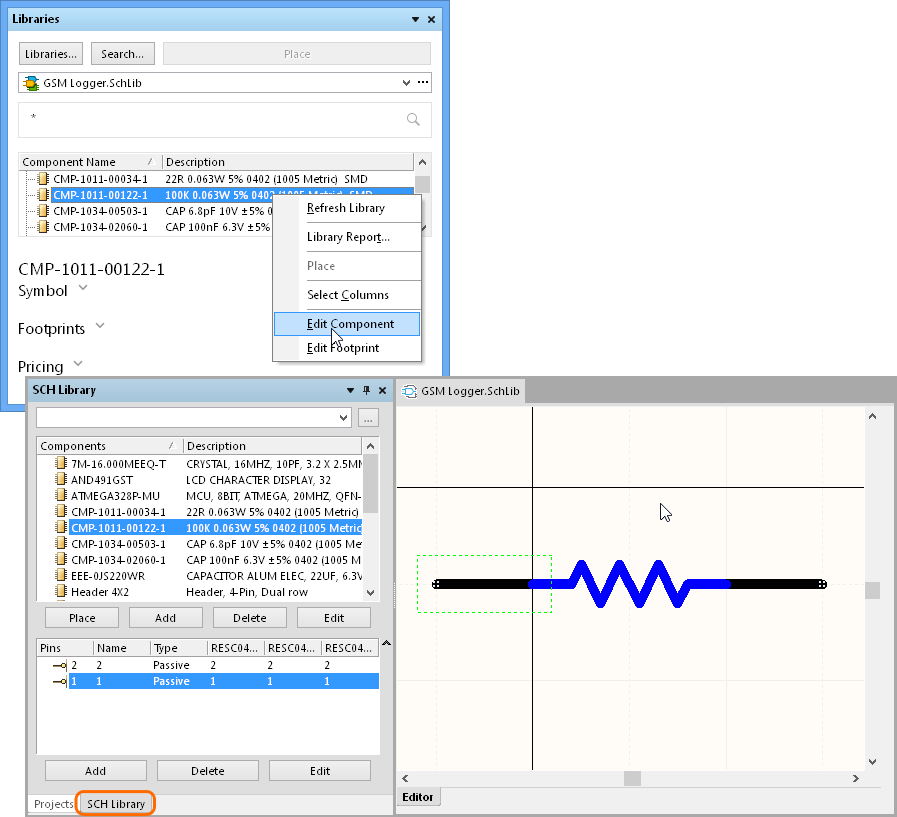
The components contained in individual Schematic or PCB libraries can be edited down to the fundamental elements and primitives.
PCBWorks will open the appropriate Library panel for the component type being edited (SCH Library panel or PCB Library panel) and load the symbol or model graphic in the editor workspace, ready for editing. The Library panel can be manually opened from the ribbon menu if necessary: View | Schematic | Library or View | PCB Library | Library.
For component editing, the system provides a comprehensive set of graphic editing tools for both schematic symbol and PCB pattern editing (available from the Home menu tab), while the Library panel delivers higher-level editing functions such as adding/deleting component entries and accessing a component’s basic elements. For schematic symbols these are the electrical pins, and for PCB patterns these are tracks, pads and 3D elements that make up the model.
Component data and linking
Beyond the inclusion of library-based symbols and patterns, a comprehensive, multi-domain component needs to contain additional information such as its base specifications, parameters and 2D/3D model links – the full descriptive data set for a unified component.
This data is stored in the schematic component itself and can be edited through the schematic Library Component Properties dialog. With the schematic library editor open this can be accessed by selecting Home | Library » Component Properties from the main menu, or by double-clicking on the component name entry in the SCH Library panel.
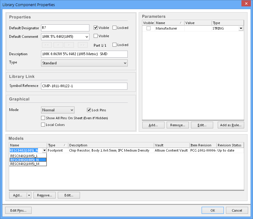
Along with a set of basic component properties, a component can have several linked models (three footprints shown here) and any number of custom Parameters added.
Perhaps the most crucial aspect to the creation (and maintenance) of a unified component are the component Schematic-PCB model links. These are established and edited in the Models section of the Library Component Properties dialog. Here 2D and 3D library models can be added, removed and edited from the section’s matching buttons and the associated PCB Model dialog.
The base schematic component can be linked to a variety of model data. Here a STEP (rather than extruded) 3D model is shown.
The component properties' PCB Model dialog allows model links to be established from a loaded library, an absolute library path, a library in the PCBWorks library search path, or by simply browsing the local system storage.
Integrated Component Libraries
The next evolutionary step in managing components in PCBWorks is effectively bringing individual Schematic and PCB libraries together as single Integrated Libraries.
These compile all the required component elements (Schematic symbols, PCB models, etc) into a single read-only library file (*.IntLib). The components contained in an Integrated Library are persistently unified across the Schematic-PCB domains, since the internal model links are permanent – that is, they cannot be broken, as is the case when component elements in separate Sch/PCB library files are linked.
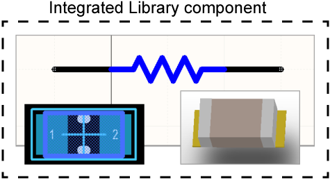
PCB models are imported into an Integrated Library component when the library is created.
In practice, an Integrated Library behaves like a read-only Schematic Library that contains (rather than links to) PCB models for each component. The library type is therefore both secure and portable.
Examples of Integrated Libraries can be found in the PCBWorks local Library folder, C:\Users\Public\Documents\Altium\PCBWorks\Library, and the Miscellaneous Integrated Libraries are usually installed by default – Miscellaneous Connectors.IntLib and Miscellaneous Devices.IntLib.
Creating an Integrated Library
A PCBWorks Integrated Library is produced from a specialised project type called a Library Package (*.LibPkg). In the simplest approach, an existing Schematic Library (with valid model links) is added to this project, which is then compiled to produce a separate Integrated Library.
The basic steps are:
- Create a Library Package project by opening a new Integrated Library project (File » New Project » Integrated Library).
- Save the project as a suitable name (File | Project Actions | Save).
- Add the existing target schematic library to the project (File | Design Documents | Add Existing Document).
- Compile the project to create the matching Integrated Library (select the package project name and choose Compile Integrated Library xx.LibPkg from the right-click context menu)
- Check for a successful compile result as indicated in the Messages panel (View | System | Messages).

An existing, valid Schematic Library (SchLib2) has been added to the MyIntLib Library Package project and compiled to create the MyIntLib Integrated Library.
Note that the Integrated Library generated by the process (saved in ../Library/Project Outputs for xx) is automatically installed in PCBWorks, ready for use. The self-contained library file, which includes the component symbols parameters and PCB models, can be safely transferred to storage or other users as part of a project or as a free standing library.
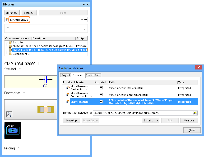
The new Integrated Library (MyIntLib) installed in PCBWorks.
Altium Vault Components
Beyond the approach of managing and working with conventional file-based component libraries, PCBWorks offers a sophisticated component management alternative in the form of an Altium Vault.
Based in on advanced server technology, the Altium Vault is a fully managed data repository that offers high-integrity storage for design elements, such as components and models, which are hosted as lifecycle-managed revisions under inherent version control. Accessible over standard networks, a licensed Vault can become the central source and destination for your library of company approved components, managed directly from PCBWorks.
The Altium Content Vault
For your immediate component needs however, you can make use of the Altium Content Vault – a read-only, fully managed repository of up-to-date components provided by Altium.
Along with providing a huge range of components available for use in your designs, the cloud-based vault content is managed by Altium in partnership with major parts suppliers. This frees you from the task of sourcing and managing component resources, since all parts are fully ratified, lifecycle managed, and offer a wide range of additional data such as current specifications, data sheets and pricing.
In practice, vault components are used in PCBWorks by simply connecting the remote Altium Content Vault, browsing or searching for the desired part in the Vault Explorer dialog and placing it into the schematic design.

The PCBWorks Vault Explorer dialog provides direct access to components in the Altium Content Vault.
See the Altium Content Vault section in the From Idea to Manufacture tutorial for an overview of connecting to the Altium Vault and placing vault components.
Component Supplier Links
While access to high quality component resources is essential to the success of a design, the symbols and models only represent the virtual equivalent of ‘real-world’ components – that is, the physical parts that are ultimately loaded into a manufactured circuit board. Deciding which actual parts are used in the design – with what specifications and from which manufacturers and suppliers, and at what price – is a crucial part of the design process that usually involves considerable research and product comparison.
PCBWorks relieves the tedium of this process while greatly improving its accuracy and relevance through the provision of Live Supplier Links. Easy and quick to implement, these are live data links established between a PCBWorks component and an item in a supplier's database of electronic components.
The Supplier Link is formed by a direct connection to supplier web services, which allows you search across all supplier databases supported by PCBWorks. When the desired part is selected, a link is added to the local Schematic component as a set of parameters – Supplier and Supplier Part Number. This link connection is then re-established each time the component is opened in a schematic or library, and is therefore guaranteed to reflect the current supplier’s data for that component.
In an existing schematic design, a component’s Supplier Links can be seen through its Properties dialog (double-click on a schematic component).

A component's Supplier Links are held as parameters in the schematic component entry as supplier and part number fields.
To see the data a component’s Supplier Link extracts from the supplier’s web services, right-click the schematic component and select Supplier Links from the associated context menu. Note that Supplier Links can be both added and removed from this dialog – see below.
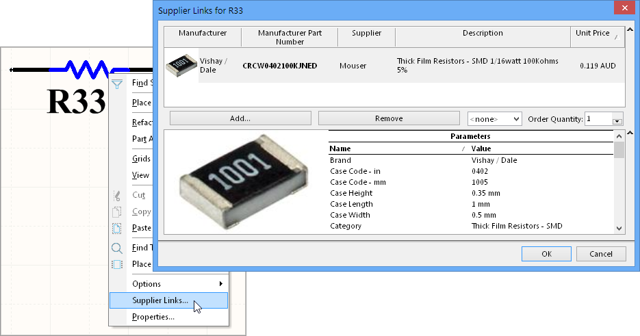
The Supplier Links dialog displays any supplier links attached to the selected component and the resulting data extracted from associated supplier web services.
Being able to establish supplier-linked component data early in the design cycle, and review this information throughout the design process, allows a designer to make valid part decisions based on current component specifications, data sheets, physical properties, and availability and pricing information. What’s more, once live Supplier Links have been added to PCBWorks components, the linked supplier data – including pricing and stock information – can be included at design release time in a Bill Of Materials (BOM).
In PCBWorks, Supplier Links can be added to components in a project or components within a Schematic Library. Supplier Links added to components in a project are exclusive to that project, whereas Supplier Links added to a library component will become available in any project that uses that library component.
Adding Supplier Links to a project
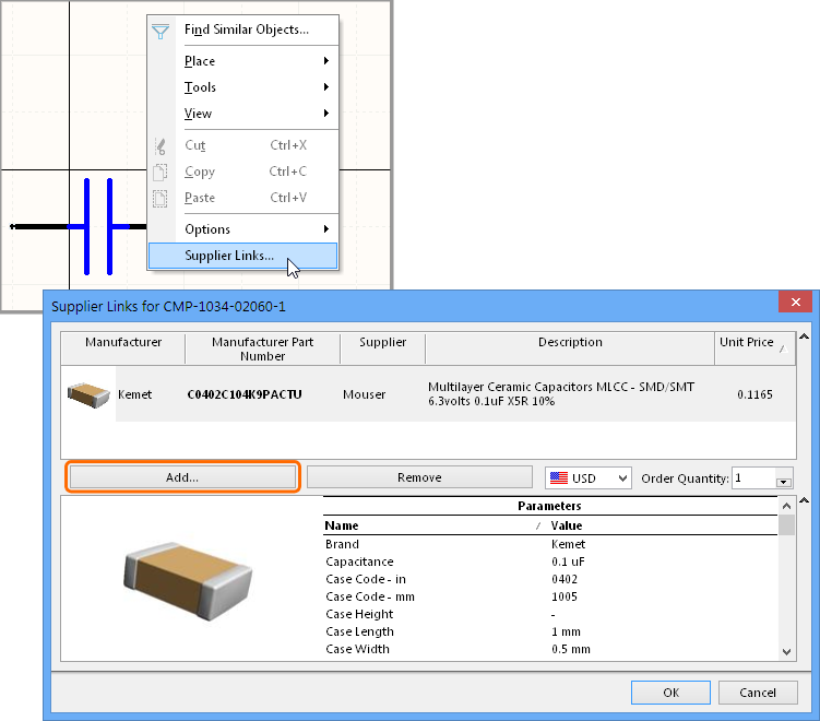
To add Supplier Links to a component in a project, select the component in the schematic, select Supplier Links from the right-click context menu, and click the Add button in the following Supplier Links.. dialog.
The dialog’s Keyword field will be pre-populated with the Comment property text for that component, which will be the nominal search string applied to the supplier databases when you select the Search button – note that the keyword string is editable.
See the Data Management – Suppliers page of the Preferences dialog for information on pre-configuring search Keywords.
When the search results have populated the upper ‘solutions’ list, you can browse through the available options to determine the optimal part selection for the project component.

When adding a supplier link to a component, the Add Supplier Links dialog shows the full list of extracted supplier entries that match the dialog's keyword search.
When the dialog is dismissed (OK) the selected supplier part information will be added to the Supplier Links dialog list, and when this dialog is subsequently dismissed (OK) the select supplier part information is added to the current component. An existing supplier link can be removed from the Supplier Links dialog list with the Remove button.
The supplier/part data is stored as the Supplier 1 and Supplier Part Number 1 parameters, as mentioned above. Note that multiple part links can be added the Supplier Links dialog list. These will be stored as successively numbered Supplier parameters in the component – that is, Supplier 1, Supplier 2, etc.
To see the resulting Supplier Link data in the project BOM, select Project | Project Actions | Generate Outputs to open the Generate output files dialog. The BOM can be both previewed and configured by selecting the BOM Configure link in the dialog. Note that different levels of supplier information can be included to the BOM by enabling and disabling data columns.
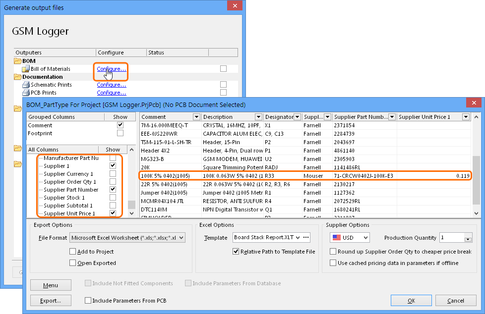
The BOM configuration dialog provides export and currency options plus a preview of the BOM contents.
Adding Supplier Links to a Library
Supplier Links are added to library components within the schematic Library Editor, instigated by opening a Schematic Library.
With the selected part opened in the editor, right-click within the workspace and select Supplier Links from the context menu. The part choices can be viewed and added from the Supplier Links dialog, as described above for adding links to a project.
Supplier Links added to a library component a stored with the component and are retrieved whenever that component is placed in a design from the Library.
Where a library component has included Supplier Links, the Libraries panel will display current pricing information for that component, sourced directly from the primary supplier – the Supplier 1 parameter for that component. This provides a convenient view of the component's current pricing information, sourced from the live supplier link, whenever that component is selected in the library for potential placement in a design.
Live pricing data is available when a library component (that has embedded supplier links) is selected in the Libraries panel.
Supplier Choices
Through agreements with range of component suppliers, Altium has enabled PCBWorks to access and search for component data from multiple sources. The web access to these supplier portals is provided by PCBWorks Extensions – plug-in software modules developed to interface with specific supplier database APIs.
From the practical perspective, a supplier Extension needs be installed and active for the Add Supplier Link dialog to load and display that supplier’s data, and to also re-access the linked data from a project or library component.
The desired supplier options also need to be enabled, which is configured through the Data Management – Suppliers page of the Data Management section in the Preferences dialog. This also provides configuration options for defining your country region, supplier login credentials (if applicable), import options and search Keywords.
Once added as PCBWorks Extensions, access to each supplier's data is enabled and configured in the Preferences dialog.
See the Data Management - Suppliers Preferences page for more information of configuring Suppliers and Supplier data.