
Interactive Routing
Contents
Parent page: PCB Dialogs
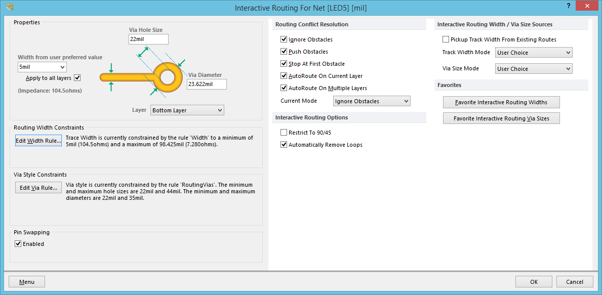
The Interactive Routing dialog.
Summary
This dialog allows the designer to change interactive routing settings for the net being routed, on-the-fly. The dialog facilitates entry of an exact track width or via size, giving the ultimate level of control, right at your fingertips. You can also check the current Interactive Routing settings, rather than having to drop out of routing and open the Preferences dialog.
Access
The dialog is accessed from the PCB Editor, by pressing the Tab key, while interactively routing a net using the Interactive Router.
Options/Controls
The dialog is essentially divided into two halves. The left-hand side provides controls relating to the interactive routing of the specific net in question, while the right-hand side provides the system-level interactive routing options that are available on the PCB Editor - Interactive Routing page of the Preferences dialog.
Left-Hand Side (Net-Specific)
Properties
- Track Width - the current track width used when routing the net on the current routing Layer. This field can be populated in the following ways:
- If the Track Width Mode is set to Rule Minimum, the field will take the minimum width defined for the corresponding layer (in the highest priority applicable routing Width rule).
- If the Track Width Mode is set to Rule Preferred, the field will take the preferred width defined for the corresponding layer (in the highest priority applicable routing Width rule).
- If the Track Width Mode is set to Rule Maximum, the field will take the maximum width defined for the corresponding layer (in the highest priority applicable routing Width rule).
- If the Track Width Mode is set to User Choice, the field will take the favorite routing width chosen (Shift+W while interactively routing).
- Choose a predefined favorite routing width from the field's drop-down list. This list reflects all predefined widths, as configured in the Favorite Interactive Routing Widths dialog.
- Enter a specific value into the field directly, on-the-fly.
- Apply to all layers - this option is used to determine the scope of the defined width, either to the specified layer only, or to all routing layers. If the User Choice feature is used, and the designer chose to apply a predefined favorite routing width to all layers, this option will be enabled.
- Via Hole Size - the current via hole size used, when dropping a via while routing this net. This field can be populated in the following ways:
- If the Via Size Mode is set to Rule Minimum, the field will take the minimum value defined for the via hole size (in the highest priority applicable Routing Via Style rule).
- If the Via Size Mode is set to Rule Preferred, the field will take the preferred value defined for the via hole size (in the highest priority applicable Routing Via Style rule).
- If the Via Size Mode is set to Rule Maximum, the field will take the maximum value defined for the via hole size (in the highest priority applicable Routing Via Style rule).
- If the Via Size Mode is set to User Choice, the field will take the hole size portion of the favorite via size chosen (Shift+V while interactively routing).
- Enter a specific value into the field directly, on-the-fly.
- Via Diameter - the current via diameter used, when dropping a via while routing this net. This field can be populated in the following ways:
- If the Via Size Mode is set to Rule Minimum, the field will take the minimum value defined for the via diameter (in the highest priority applicable Routing Via Style rule).
- If the Via Size Mode is set to Rule Preferred, the field will take the preferred value defined for the via diameter (in the highest priority applicable Routing Via Style rule).
- If the Via Size Mode is set to Rule Maximum, the field will take the maximum value defined for the via diameter (in the highest priority applicable Routing Via Style rule).
- If the Via Size Mode is set to User Choice, the field will take the diameter portion of the favorite via size chosen (Shift+V while interactively routing).
- Enter a specific value into the field directly, on-the-fly.
- Layer - the current routing layer. Use the field's drop-down to switch to routing on a different layer (a via will be dropped to the target layer, with sizing as per the Via Hole Size and Via Diameter fields).
Routing Width Constraints
This region of the dialog displays information about the design rule that is being applied to the net's routing track width, in terms of:
- The name of the rule.
- The minimum and maximum permissable track widths for the current routing layer. Values are presented in workspace units, as well as calculated impedance values.
- Edit Width Rule - click this button to access the Edit PCB Rule dialog, with the applicable Width rule loaded. From here, you can modify the scope and/or constraints of the rule as required.
Via Style Constraints
This region of the dialog displays information about the design rule that is being applied to the net's routing via style, in terms of:
- The name of the rule.
- The minimum and maximum permissable hole sizes for the via.
- The minimum and maximum permissable diameters for the via.
- Edit Via Rule - click this button to access the Edit PCB Rule dialog, with the applicable Routing Via Style rule loaded. From here, you can modify the scope and/or constraints of the rule as required.
Pin Swapping
- Enabled - enable this option to allow pin swapping for components whose pins (pads) are members of this net.
Menu Commands
The following commands for this side of the dialog are available from the menu associated to the Menu button:
- Edit Width Rule - use this command to access the Edit PCB Rule dialog, with the currently applicable Width rule loaded. From here, you can modify the scope and/or constraints of the rule as required.
- Edit Via Rule - use this command to access the Edit PCB Rule dialog, with the currently applicable Routing Via Style rule loaded. From here, you can modify the scope and/or constraints of the rule as required.
- Add Width Rule - use this command to create a new Width rule. The Edit PCB Rule dialog will appear, from where to define the rule as required.
- Add Via Rule - use this command to create a new Routing Via Style rule. The Edit PCB Rule dialog will appear, from where to define the rule as required.
- Net Properties - use this command to access the Edit Net dialog, with which to browse, and modify, the properties of the net.
Right-Hand Side (System Preferences)
Routing Conflict Resolution
- Ignore Obstacles - enable this option to have the Interactive Router allow the track to pass through obstacles while routing.
- Push Obstacles - enable this option to have the Interactive Router move existing tracks out of the way while routing. This mode can also push vias to make way for the new routing. If this mode cannot push an obstacle without causing violation, an indicator appears to show the route is blocked.
- Stop At First Obstacle - enable this option to have the Interactive Router stop routing when it encounters the first obstacle in its path.
- AutoRoute On Current Layer - enable this option to have the Interactive Router autoroute to the current cursor location on the current layer.
- AutoRoute On Multiple Layers - enable this option to have the Interactive Router autoroute to the current cursor location across different layers. Vias will be placed as required to change to alternate signal layers.
- Current Mode - this field displays the current Routing Conflict Resolution mode chosen, when using the Interactive Router. Use the associated drop-down to change the mode as required.
Interactive Routing Options
- Restrict To 90/45 - enable this option to restrict the routing to 90 degrees and 45 degrees only.
- Automatically Remove Loops - enable this option to automatically remove any redundant loops that are created during manual routing. This allows a connection to be re-routed without having to manually remove redundant tracks.
Interactive Routing Width / Via Size Sources
- Pickup Track Width From Existing Routes - enable this option to use the existing track width when routing from a placed track. That is, even if the current routing width is different to the existing track, the existing track width will be adopted when you continue the route from it.
- Track Width Mode - use this field to choose a track width mode for interactive routing. The available modes are:
User Choice- with this mode enabled, the width is determined from the width selected in the Choose Width dialog, accessed by pressing Shift+W while routing.Rule Minimum- with this mode enabled, the minimum width defined for the corresponding layer (in the highest priority applicable routing Width rule) will be used.Rule Preferred- with this mode enabled, the preferred width defined for the corresponding layer (in the highest priority applicable routing Width rule) will be used.Rule Maximum- with this mode enabled, the maximum width defined for the corresponding layer (in the highest priority applicable routing Width rule) will be used.
- Via Size Mode - use this field to choose a via size mode for interactive routing. The available modes are:
User Choice- with this mode enabled, the via size is determined from the size selected in the Choose Via Size dialog, accessed by pressing Shift+V while routing.Rule Minimum- with this mode enabled, the minimum values defined for the via diameter and hole size (in the highest priority applicable Routing Via Style rule) will be used.Rule Preferred- with this mode enabled, the preferred values defined for the via diameter and hole size (in the highest priority applicable Routing Via Style rule) will be used.Rule Maximum- with this mode enabled, the maximum values defined for the via diameter and hole size (in the highest priority applicable Routing Via Style rule) will be used.
Favorites
- Favorite Interactive Routing Widths - click this button to access the Favorite Interactive Routing Widths dialog, with which to predefine your favorite track widths, for use when interactively routing a board, using the Interactive Router.
- Favorite Interactive Routing Via Sizes - click this button to access the Favorite Interactive Via Sizes dialog, with which to predefine tyour favorite via sizes, for use when interactively routing a board, using the Interactive Router.