
PCB Editor - Display
Contents
Related dialogs:
Parent page: PCB Preferences
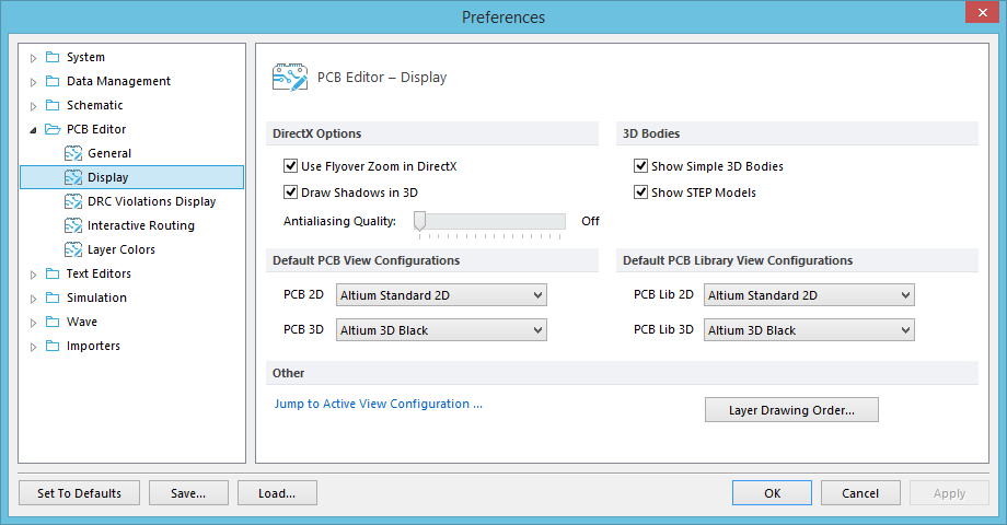
The PCB Editor - Display page of the Preferences dialog.
Summary
The PCB Editor – Display page of the Preferences dialog provides a range of options relating to the visual functionality the PCB workspace.
Access
The PCB Editor – Display page is part of the main Preferences dialog (File | ![]() ) and is accessed by clicking the Display entry under the PCB Editor folder, in the left hand pane of the dialog.
) and is accessed by clicking the Display entry under the PCB Editor folder, in the left hand pane of the dialog.
Options/Controls
DirectX Options
- Use Flyover Zoom in DirectX - Check this option to enable the Flyover Zoom function in DirectX.
- Draw Shadows in 3D - Enable to apply a shadow effect to objects when viewing in 3D mode.
- Antialiasing Quality - Use the scroll bar to adjust the antialiasing degree in 3D. Move the slider fully to the right to disable antialiasing.
3D Bodies
- Show Simple 3D Bodies - Enable to display simple (extruded) 3D bodies.
- Show STEP Models - Enable to display 3D STEP models included in the design.
Default PCB View Configurations
- PCB 2D - Shows the default 2D mode view configuration that is applied when a PCB document that does not have a specific view configuration is opened, or when a new PCB document is created. Select to view and choose a default 2D view configuration from the list.
- PCB 3D - Shows the default 3D mode view configuration that is applied when a PCB document that does not have a specific view configuration is opened, or when a new PCB document is created. Select to view and choose a default 3D view configuration from the list.
Default PCB Library View Configurations
- PCB Lib 2D - Shows the default 2D mode view configuration that is applied when a PCB Library that does not have a specific view configuration is opened, or when a new PCB Library document is created. Select to view and choose a default 2D view configuration from the list.
- PCB Lib 3D - Shows the default 3D mode view configuration that is applied when a PCB Library that does not have a specific view configuration is opened, or when a new PCB Library is created. Select to view and choose a default 3D view configuration from the list.
Other
- Jump to Active View Configuration - Click this text to jump the View Configurations dialog. The View Options tab of the dialog will be presented, providing additional display-related options for the PCB workspace.
- Layer Drawing Order - Click to open the Layer Drawing Order dialog, which allows the order in which layers are redrawn on the screen to be defined. The order that the layers appear in the list is the order in which they will be redrawn. The layer at the top of the list is the layer which will appear on top of all other layers on the screen.