
Radial Diameter Dimension
Contents
Parent page: Dimension
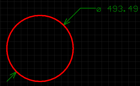
A placed Radial Diameter dimension.
Summary
A radial diameter dimension is a group design object. It allows for the dimensioning of an arc or circle with respect to the diameter, rather than the radius. The dimension can be placed either internally or externally, in relation to the circumference of the arc/circle.
Availability
Radial Diameter dimension objects are available for placement in the PCB Editor only, by clicking Home | Dimension | ![]() and selecting Radial Diameter from the drop-down list.
and selecting Radial Diameter from the drop-down list.
Placement
After launching the command, the cursor will change to a cross-hair and you will enter dimension placement mode. Placement is made by performing the following sequence of actions:
- Position the cursor and click or press Enter to anchor the dimension to the desired arc or circle.
- Move the dimension's arrow pointer to the desired location around the arc or circle. The arrow can be placed either inside or outside and movement is in accordance with the Angular Step value in the Radial Diameter Dimension dialog. When the required position has been attained, click or press Enter to lock the arrow in place.
- The text can now be initially positioned in relation to the tail of the arrow pointer. Move the text into the required position and click or press Enter to complete placement.
- Continue placing further radial diameter dimensions, or right-click or press Esc to exit placement mode.
Additional actions that can be performed during placement are:
- Press the + and - keys (on the numeric keypad) to cycle forward and backward through all visible layers in the design respectively – to change placement layer quickly.
- Press the Tab key to access an associated properties dialog, from where properties for the dimension can be changed on-the-fly.
Graphical Editing
This method of editing allows you to select a placed radial diameter dimension object directly in the workspace and change properties such as the position of its text and its reference point, graphically.
When a radial diameter dimension object is selected, the following editing handles are available:
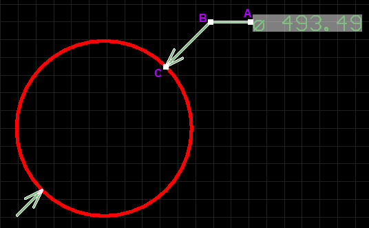
A selected Radial Diameter Dimension.
- Click & drag A to adjust the leader position, relative to the 'tail' of the arrow pointer.
- Click & drag B to adjust the position of the arrow pointer around the circumference of the circle or arc or change the length of the arrow leader line.
- Click & drag C to move the start point of the dimension.
If the radial diameter dimension object is totally non-referenced (i.e. it is not attached to a reference design object) click anywhere on it – away from editing handles – and drag to reposition it. While dragging, the radial diameter dimension can be rotated or mirrored:
- Press the Spacebar to rotate the radial diameter dimension anti-clockwise or Shift+Spacebar for clockwise rotation. Rotation is in accordance with the value for the Rotation Step, defined on the PCB Editor – General page of the Preferences dialog.
- Press the X or Y keys to mirror the radial diameter dimension along the X-axis or Y-axis respectively.
Non-Graphical Editing
The following methods of non-graphical editing are available:
Via an Associated Properties Dialog
Dialog page: Radial Diameter Dimension
This method of editing uses the following dialog to modify the properties of a radial diameter dimension object.
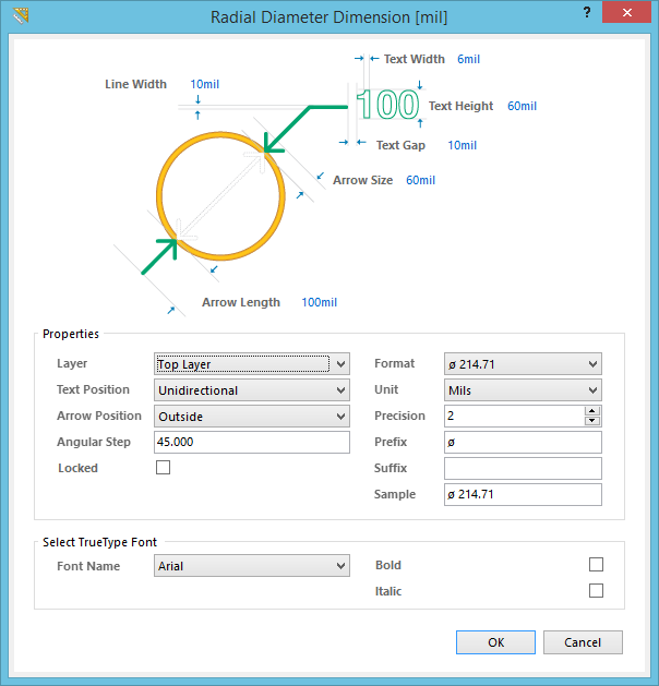
The Radial Diameter Dimension dialog.
The Radial Diameter Dimension dialog can be accessed during placement by pressing the Tab key.
After placement, the dialog can be accessed in one of the following ways:
- Double-clicking on the placed radial diameter dimension object.
- Placing the cursor over the radial diameter dimension object, right-clicking and choosing Properties from the context menu.
Via the PCB Inspector Panel
Panel page: PCB Inspector
The PCB Inspector panel enables the designer to interrogate and edit the properties of one or more design objects in the active document. Used in conjunction with appropriate filtering, the panel can be used to make changes to multiple objects of the same kind, from one convenient location.
Notes
- A radial diameter dimension object can be moved in the following ways:
- Selecting both the dimension object and the object that is being dimensioned. The whole can be dragged to a new location as required.
- Selecting the object that is being dimensioned only. The dimension text will follow the object in its alignment plane only. The dimension pointer and tail will expand/contract to keep the relationship between dimension and object being dimensioned.
- Selecting the dimension object only. It is important to note that the dimension cannot be moved on its own if it is referenced by a design object. To move the dimension only, it must first be detached from the object it is dimensioning.
- The dimension's value automatically updates as the radius of the reference arc or circle changes.
- When the reference arc or circle to which a radial diameter dimension object is attached is deleted, a dialog will appear, asking whether the dimension should also be deleted. If the dimension is not deleted, it remains in the workspace, but non-referenced.