PCBLIB Inspector
Contents
The natural partners to the PCBLIB Inspector panel are the PCBLIB Filter panel and the PCB Library panel:
Parent page: PCB Panels

Select PCB objects to populate the PCBLIB Inspector panel with objects to be
viewed or edited.
Summary
The PCBLIB Inspector panel enables you to interrogate and edit the properties of one or more design objects in the active PCB Library document. When used in conjunction with appropriate filtering, the panel can be used to make changes to multiple objects of the same kind, from one convenient location. The panel is a natural partner to the PCBLIB Filter panel.
Panel access
Access the PCBLIB Inspector panel by:
- Clicking View | PCB Library| from the main menus.
- Using the F11 keyboard shortcut.
Defining panel display scope
The PCBLIB Inspector panel allows you to define which objects are displayed in the panel (the display scope) via filtering controls. This can be accessed using the underlined control at the top of the panel.
![]()
You may have a large quantity of objects selected in the workspace that are of differing type. Out of all such objects, you may wish to edit the properties of certain object types only, without losing or having to alter your selection.
Use the Include link context menu to choose which object types to include in the panel for display and editing - either all objects or specific objects. To choose one or more specific object types, enable the Display only option and then enable the check box next to the required object(s) in the list beneath. The list will only contain those object types currently selected in the main workspace.
When specific object types have been enabled for display, the control will reflect the choice by listing the enabled types, separated by commas.
![]()
Inspecting object attributes
The main regions of the PCBLIB Inspector panel show sections of attributes for objects falling under the defined display scope.
Clicking on a single object in the PCB library editor window will select that object and display its associated attributes in the PCBLIB Inspector panel. Information is displayed under the following common collapsible sections:
Kind
This panel section contains one entry only, relating to the kind of design object that is being 'inspected'. For example, clicking on a component in the workspace will display the entry Component, clicking on a component designator will display the entry Text, and so on.
Object Specific
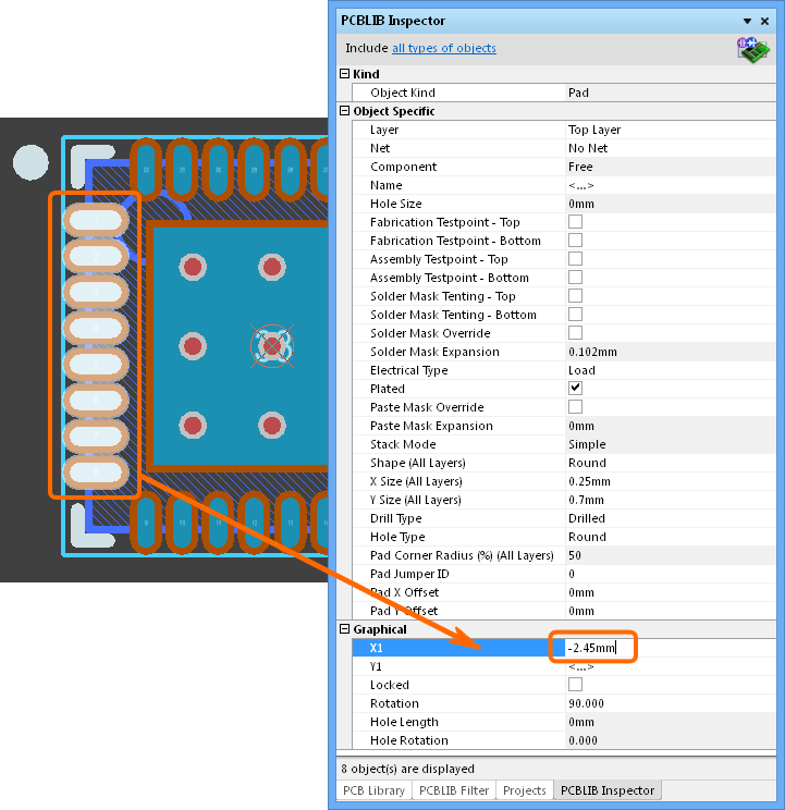
This section contains attributes specific to the object being inspected and which are not graphical attributes. For example, selecting a Pad will display the attributes that are specific to a Pad, including:
- Layer
- Name (the pad designator)
- Hole Size
- Solder Mask settings
- Electrical Type
- Drill/Hole Type
- etc...
Other selected objects will have different attributes displayed. For example, selecting a Via object will display attributes such as Via Diameter and Start/Finish Layer.
Graphical
This section of the panel contains graphical attributes of the selected object. Attributes here may include the location of the object, its rotation and dimensions, and whether it is locked.
Editing object attributes
The attributes of a selected object can be edited through the relevant entry in the panel. The change will take effect once you click outside of the field being edited. This is one of the advantages of using the panel to edit object properties – the panel will remain open, allowing you to change attribute after attribute, as needed, without having to close and reopen an object's properties dialog each time.
However the main advantage of using the panel for editing is that multiple objects can be edited from the one place, without having to edit, through dialogs, one object at a time. Selected objects can be of the same or differing type. Those attributes that are common to all objects in the selection will be displayed in the panel. Common attributes that have differing values between objects will be displayed as <...>. As the attributes are edited as required, the changes made will be conveyed instantly to each object in the selection.
Filtering (using the PCBLIB Filter panel) can be used to target a specific group of objects in the design and the PCBLIB Inspector panel then used to edit the attributes for these multiple objects, directly.
Multiple objects can be inspected and edited in the panel by:
- Manually selecting several objects in the workspace using standard Ctrl+click and Shift+click techniques.
- Using the mouse to 'lasso' a group of objects using the click+drag method. Multiple groups can be selected using Ctrl+click+drag and Shift+click+drag.
- Selecting all objects in a component using Home | Clipboard | Select » All (or Ctrl+A), and then applying the panel's filter (Include...) to target specific objects – for example; Pads.
Editing attributes with numeric values
For a numerical-based attribute of a selected object, the simplest modification to that attribute's value is made by typing a new value to replace the existing one. The plus and minus operators can be used to specify the value's sign. A value entered without a specified sign is assumed to be positive. Therefore entering 20 is the same as entering +20.
A value can be entered with specific units of measurement and the software will convert the value into the current units defined for the document. If no units are specified, the default units set for the document will be used.
When multiple objects are selected, changing a common attribute will effect all those selected. For example, to shift a set of selected pads to left or right, edit their common X1 position attribute.
Batch replacement of string-based attributes
There are occasions when it's desirable to modify a string-based attribute that is common to multiple selected objects. For example to rename the designators of selected header components from P1, P2, P3, etc, to HDR1, HDR2, HDR3, etc. To perform this type of batch replacement, the use of string substitution syntax is supported in the panel.
A string substitution entry is enclosed in braces and has the form: {oldstring=newstring}
An entry of this form causes all occurrences of 'oldstring' found in the attribute's value to be replaced with 'newstring'. In the case of the designators example, you would enter {P=HDR) in the value field for the Name attribute.
Should you wish to replace multiple, differing string portions in the same target string, type multiple substitution entries in sequence, with each enclosed in its own set of curly braces. The software takes this entry and effectively performs a batch substitution – substituting for the first expression, then the second, and so on.
Smart Editing of string-based attributes
The PCBLIB Inspector panel offers further support for string modification through its Smart Edit feature.
Simply click on a shared attribute with different values for the selected objects (initially shown as <...>), whose value is a string. A ![]() button will become available at the far right of the cell. Click on this button to access the Smart Edit dialog.
button will become available at the far right of the cell. Click on this button to access the Smart Edit dialog.
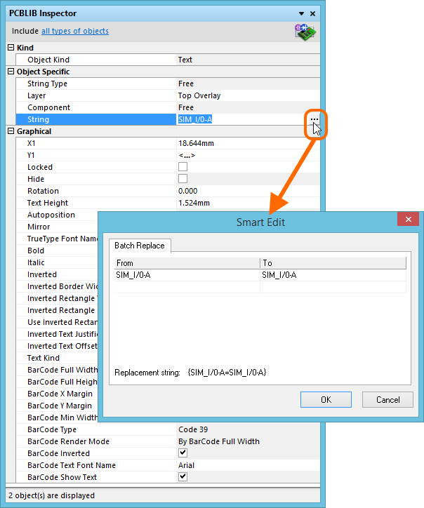
The Smart Edit dialog offers a streamlined method for performing multiple string modifications,
accessed from the Batch Replace tab.
The Batch Replace tab provides simple straightforward substitution, along the lines of the string substitution mentioned previously (but without having to enter the curly braces). Click in the From field and enter the portion of the current string that you wish to replace. Click in the To field and enter the string to be used as the replacement. The familiar string substitution syntax is displayed at the bottom of the tab.
For example, consider the Top Overlay text for six pad connections shown in the image below, which have the prefix SIM_ that needs to be changed Sm_. In this case, select the components, click on the String attribute in the panel (as shown in the image above) and access the Smart Edit dialog. Then on the Batch Replace tab, enter SIM in the From field and Sm in the To field (the replacement string is therefore {SIM=Sm}). After clicking OK, the designators will be modified accordingly.
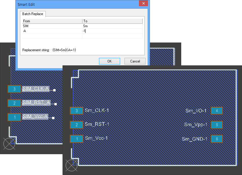
As with basic string substitution, the Batch Replace tab provides for replacement of multiple, differing string portions in the same target string. Enter the
various substitutions as distinct From-To entries. In the above example, the string suffix has been entered as another batch substitution change entry, from -A to -1.