Formatting Tools
Parent page: Commands
The Formatting Tools include a wide array of customization options including font name, size, style, and color, as well as line width and type.
Summary
Use the Formatting Tools commands to customize your workspace based on personal preference and/or design needs. Some formatting options include changing font color for designator text or updating an object's fill color; increasing text size to make it more legible or decreasing it to reduce clutter; and highlighting specific objects by changing their line style to dots or dashes instead of solid or changing the line width.
Details
Formatting Tools can be accessed from the ribbon under Home | Font, Home | Appearance, and Tools | Navigation. Certain Formatting Tools, such as color, can also be accessed through individual objects' associated dialog. For example, opening the Net Label dialog allows you to set the color and font name for a selected net. However, the formatting tools in the ribbon typically offer more options than an object's dialog.
You can also edit the common attributes of different objects at the same time. Click and drag a rectangle or click+shift to select multiple objects at once. Once multiple items are selected, formattable, common attributes will be available to edit on the Font and/or Appearance sections of the Home ribbon.
Formatting Text
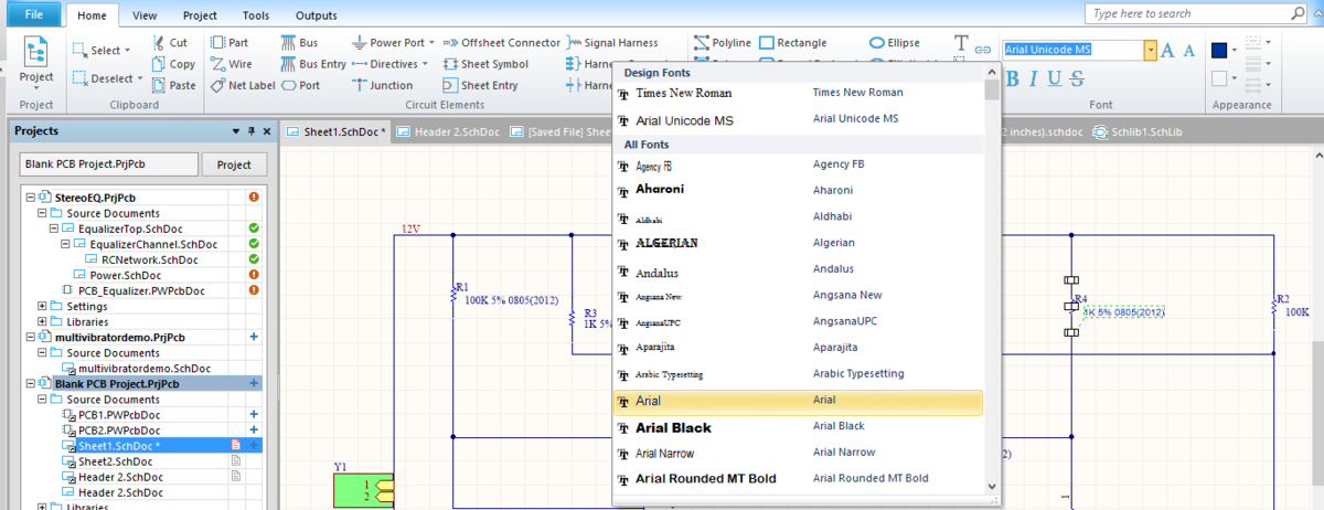
You can use color, font name, font style, and/or font size to organize and differentiate the different strings of text on your schematic.

Different Font formatting options.
Font name, size, and style can be accessed from the Home | Font section of the ribbon. Font color can be customized using the Home | Appearance section of the ribbon. Color, and sometimes font name, can also be customized using the text's associated dialog box. For example, by double clicking on a component's designator or comment text, you can open the Parameter Properties dialog which allows you to set both the font name and color. The same applies to annotation text, net labels, and sheet symbol filenames, with their respective dialogs.
| Command | Behavior |
|---|---|
Font name | A drop down menu will present with different font name selections. Highlight and select one to view the change in the schematic document. |
| Apply bold formatting to highlighted text. | |
| Apply Italic formatting to highlighted text. | |
| Apply Underline formatting to highlighted text. | |
| Apply | |
| Incrementally increase highlighted text's font size. | |
| Incrementally decrease highlighted text's font size. | |
| When text is selected, choose a preset color or select More Colors to open the Choose Colors dialog. The dialog allows you to choose from a wider range of preset colors or custom select a new color which can be saved to a custom palette for re-use. |
Formatting Objects
As with text, you can adjust the color of objects such as circuit elements and graphical elements. Additionally, you can also format line with, line style, and line end style. Line styles can be used to differentiate a Line as a marker or arrow to point at or outline something on the schematic.
Appearance Options.
These formatting tools can be accessed from the Home | Appearance section of the ribbon. Like the text formatting, formatting changes can also be made from an object's dialog.
| Command | Behavior |
|---|---|
| When an object is selected, set the outline color. Choose a preset color or select More Colors to open the Choose Colors dialog. The dialog allows you to choose from a wider range of preset colors or custom select a new color which can be saved to a custom palette for re-use. | |
| When an oblect is selected, set the fill color. Choose a preset color or select More Colors to open the Choose Colors dialog. The dialog allows you to choose from a wider range of preset colors or custom select a new color which can be saved to a custom palette for re-use. | |
| Opens a drop down of line style choices; set whether the line is solid, dots, or dashes. | |
| Opens a drop down of line width choices; set how wide the line is. Can also be used to increase the border width of an object. | |
| Opens a drop down of line end styles; set the line end style from choices such as arrows, circles, or squares. |
Formatting Connections
Tools used to format connections allow you to easily view connections on your schematic.
These formatting tools can be access from the Tools | Navigation section of the ribbon.
| Command | Behavior |
|---|---|
| The cursor will appear as a crosshair. Select an object on your schematic with the crosshair and it will highlight all of the object's connections in purple. Clicking another object to view its connections will remove the highlighting from your previously selected connections and only highlight connections for the new selection. | |
| Remove the highlighting from selected connections on the board. |