
Harness Entry
Parent page: Sch Dialogs
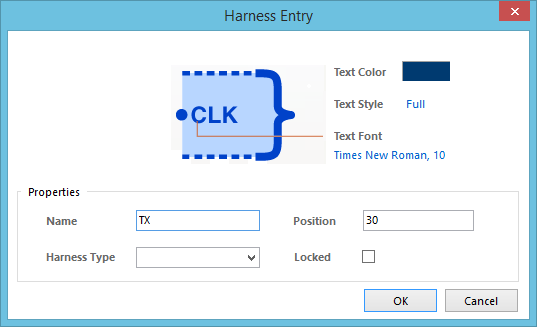
The Harness Entry dialog.
Summary
This dialog allows the designer to specify the properties of a Harness Entry object. A Harness Entry is an electrical design primitive that is placed within a Harness Connector. A Harness Entry is the connection point through which signals - through wires, buses, and other signal harnesses - are combined to form a higher level Signal Harness. Signal Harnesses enable the logical grouping of different signals for increased flexibility and streamlined design.
Access
The Harness Entry dialog can be accessed during placement by pressing the Tab key (while the harness entry is still floating on the cursor, and while it is within the bounds of a harness connector).
After placement, the dialog can be accessed in one of the following ways:
- Double-clicking on the placed harness entry object.
- Placing the cursor over the harness entry object, right-clicking and choosing Properties from the context menu.
Options/Controls
- Text Color - click the color sample to change the text color for the harness entry, using the standard Choose Color dialog.
- Text Style - use this field to determine how the text for the harness entry is displayed, when bus syntax is used. Choose from the following options:
- Full - choose this option to display the net identifier information in full. For example the N[0..7] net identifier string will be shown as N[0..7].
- Prefix - choose this option to display only the prefix of the net identifier, ignoring the bracketed portion. For example the N[0..7] net identifier string will be shown as N.
- Text Font - this control serves two purposes. Firstly, it reflects the currently chosen font for the text in terms of Font Name, Font Size and Font Style. Secondly, when clicked it provides access to the standard Font dialog, from where to change the font as required.
Properties
- Name - the current name of the harness entry. This name uniquely identifies this harness entry within its parent harness connector. All entries withn the same harness connector must be unique.
- Position - the current position of the harness entry in relation to the top of the harness connector. Enter a greater value to move the harness entry further down.
- Harness Type - this field is used to specify a Harness Type for a particular signal harness system in the design. It is typically left blank when a wire or bus is connected to the harness entry, used only when another signal harness itself is connected. The Harness Type itself is defined either manually in the associated Harness Definition File, or as part of the properties of a Harness Connector. The associated drop-down lists all currently defined Harness Types detected across the source schematic documents of the active project.
- Locked - enable this option to protect the harness entry from being edited graphically.