
Place Part
Contents
Other Related Resources
Parent page: Sch Dialogs
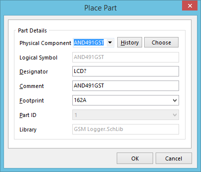
The Place Part dialog.
Summary
This dialog allows the designer to choose a schematic part and configure related attributes, prior to placement on the active schematic document.
Access
The dialog can be accessed from the Schematic Editor, by clicking Home | Circuit Elements | ![]() , from the main menus. Alternatively, right-click in the workspace and use the Place » Part command from the context menu.
, from the main menus. Alternatively, right-click in the workspace and use the Place » Part command from the context menu.
Options/Controls
- Physical Component - the name of the design component being placed. Type the name of the component directly into the field, select a previously placed component from an historical list, or browse for it among the set of Available Libraries. The field's associated drop-down will list historically placed components.
- History - click this button to access the Placed Parts History dialog, listing all previously placed components. Select a component in this dialog and click OK to have it loaded ready for placement back in the main Place Part dialog.
- Choose - click this button to access the Browse Libraries dialog, from where you can browse for a component through all available libraries (project libraries, installed libraries, and libraries found along specified search paths). Select a component in this dialog and click OK to have it loaded ready for placement back in the main Place Part dialog.
- Logical Symbol - this uneditable field presents the name of the logical symbol, which is the symbolic representation of the physical component in the schematic domain.
- Designator - the current designator that will be used for the next placed instance of the chosen component. By default, the undesignated form of designator associated with the type of component will be used, such as U?, C?, R?, Q?. By specifying the designator prior to placement, you will be able to place multiple instances, and the designator will increment, resulting in uniquely designated components.
- Comment - use this field to give the component a meaningful comment, which might be its part number (for a specific IC package), or a value (for a generic component such as a resistor, capacitor, or inductor).
- Footprint - the footprint model that will be used to represent the component in the PCB domain. If the component has multiple footprints (or more precisely 2D/3D Component models) linked to it, these will be listed on the field's drop-down. Simply choose the model you wish to set as the current model.
- Part ID - for a multi-part component, this field allows you to choose which part to place, from the associated drop-down listing. For a single part component, this field will simply reflect this with the entry 1, and be grayed-out.
- Library - this uneditable field presents the name of the library in which the chosen component resides.