
Edit Component Links
Contents
Parent page: WorkspaceManager Dialogs
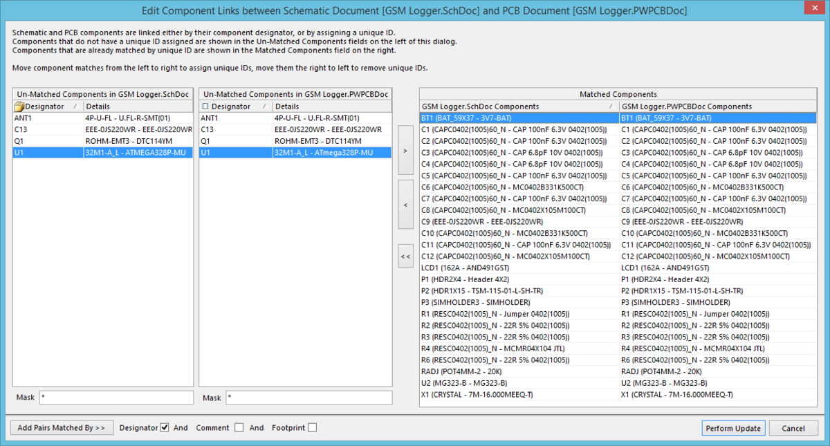
The Edit Component Links dialog
Summary
This dialog allows the designer to check and control the status of the links between components in the schematic and PCB domains. When a component is placed on a schematic sheet, it is automatically given a unique ID. As a precursor to comparison, PCBWorks scans the source schematic and target PCB documents for linked components. These are components that have been previously synchronized with one another and share a unique ID. This dialog provides controls to manually match and link components between the two domains.
Access
The Edit Component Links dialog is accessedby clicking Project » Component Links in the PCB editor.
Options/Controls
- Un-Matched Components - this, left-hand side of the dialog, presents components that are currently unmatched. Two lists are used to cater for unmatched components on the source schematic documents (left) and those unmatched components on the target PCB document (right). Each component is listed in terms of its designator, footprint name, and comment.
- Matched Components - this region, on the right-hand side of the dialog, presents all components that are currently matched. The region's two columns simply list the schematic components on the left, and the PCB components on the right, with each entry consisting of designator, footprint name, and comment.
- Match Selected - click this button to manually match the currently selected unmatched schematic component, with the currently selected unmatched PCB component. The entries will disappear from their respective Un-Matched Components lists, and a single entry for the two will be added to the Matched Components region.
- Un-Match Selected - click this button to 'un-match' the currently selected component entries in the Matched Components region. The entries will be removed from the region, and the constituent components added back to their respective Un-Matched Components region lists.
- Un-Match All - click this button to 'un-match' all components currently listed in the Matched Components region. The entries will be removed from the region, and the constituent components added back to their respective Un-Matched Components region lists.
- Add Pairs Matched By - click this button to automatically match unmatched components in accordance with the selected options to the right. Matching can be attempted by any combination of Designator, Comment, and Footprint. Successful matching will result in applicable entries disappearing from their respective Un-Matched Components lists, and a single entry for each linked couple being added to the Matched Components region.
- Perform Update - click this button to effect changes made to linking. If you have un-matched any components, a confirmation dialog will appear, alerting you to the fact that some existing component associations will be broken by proceeding. To carry on, click Yes. An information dialog will display, showing how many links were modified and/or how many links were removed.