
Gerber X2 Setup
Contents
Parent page: WorkspaceManager Dialogs
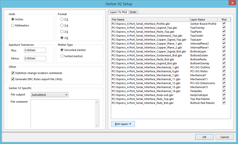
The Gerber X2 Setup dialog.
Summary
This dialog allows the designer to specify the layers to be plotted, and configure related additional options, when generating output from the active PCB in Gerber X2 format. Gerber X2 is a direct, and much advanced, evolution of the existing Gerber RS-274X standard and adds a large range of additional data for PCB fabrication and assembly.
Access
The dialog is accessed from the PCB Editor by clicking Outputs | Fabrication | ![]() , from the main menus.
, from the main menus.
Options/Controls
Units
Use this region to choose the inherent units used in the generated file:
- Inches - enable this option to use imperial units, where all work is done in mils (1/1000 inch).
- Millimeters - enable this option to use metric units, where all work is done in millimetres.
Format
Use this region to specify the numerical precision of the plot coordinates in the Gerber file. The following precisions are supported:
- 2:3 - providing a resolution of 1 mil (1/1000 inch).
- 2:4 - providing a resolution of 0.1 mil.
- 2:5 - providing a resolution of 0.01 mil.
- 2:6 - providing a resolution of 0.001 mil.
Aperture Tolerances
Use the options in this region to set the tolerance range used when matching apertures for each item in the plots.
- Plus - define the positive tolerance for aperture matching.
- Minus - define the negative tolerance for aperture matching.
Plotter Type
Use this region to specify the target photoplotter type:
- Unsorted (raster) - use raster machine (default).
- Sorted (vector) - use vector machine.
Other
- Optimize change location commands – when this option is enabled, X or Y location data is not included if it does not change from one object to the next.
- Generate DRC Rules export file (.RUL) - enable this option to generate a DRC Rules Export file. The report details the design rules defined for the source PCB document from which the Gerber data is being generated.
Gerber X2 Specific
- File Subject – use this field to nominate the file type, which is included as a
Partattribute in the Gerber X2 outputs. The field's drop-down list provides the following choices:- None
- Autodetect – automatically assigns an attribute from the below list, based on the type of board file. For example, a PCB document containing a single board design will be assigned the
Singlepart attribute. - Single – a Single PCB.
- CustomerPanel – a board array or shipping panel.
- ProductionPanel – a working panel or fabrication panel.
- Coupon – a Coupon (performance test board associated with a main board design).
- Other – none of the above. In the file, a string appended to the attribute informally indicates the part.
- File Comment – enter a comment that will be included as an attribute in the generated outputs.
Layers To Plot
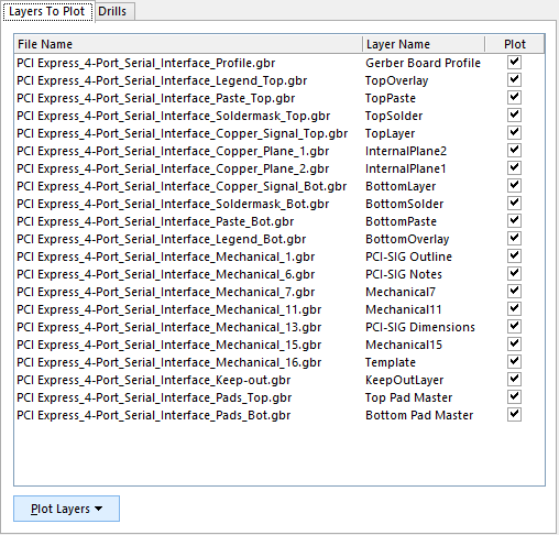
All layers for the current board design are listed on the Layers To Plot tab.
This tabbed region of the dialog allows you to configure which layers to plot in the Gerber X2 output for the current PCB document.
- Layers List - a listing of layers in the current PCB. Each layer is presented in terms of the following:
- File name – the individual Gerber output file name. This uses a naming convention that is indicative of the file’s function and uses a
.gbrextension. Naming is based on the project name, layer and function, and uses an underscore character as a descriptive separator. - Layer Name – the layer name that applies to the output file, as defined by the board’s layer stack.
- Plot – enable this option to include a Gerber plot for that layer in the generated output. Disable to exclude the plot from being generated for that layer.
- File name – the individual Gerber output file name. This uses a naming convention that is indicative of the file’s function and uses a
- Plot Layers - click this button to access a menu of commands that allow the Plot field for all layers in the list to be enabled/disabled en-masse:
- All On - use this command to enable the Plot option for all layers, (create Gerber plots for all listed layers).
- All Off - use this command to disable the Plot option for all layers, (create no Gerber plots).
- Used On - use this command to enable the Plot option for all used layers, (create Gerber plots for all listed layers that are actively being used in the design).
Drills
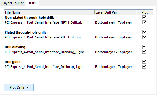
All relevant Drill files for the current board design are listed on the Drills tab.
This tabbed region of the dialog includes the relevant drill files that will be generated for the current board design, which can be selected for generation on an individual or group basis.
- Drills List - a listing of drill files for the current PCB. This includes Drill drawing and Guide outputs. A drill drawing is a plot of the location of each drill site on the PCB, with each drill size plotted with a different symbol, whereas a drill guide marks each site with a small cross. Separate files are also available for plated and non-plated through-holes, and blind/buried vias if included in the design. Each drill file is presented in terms of the following:
- File Name – the individual Drill output file name, constructed to comply with the Gerber X2 standard.
- Drill Layer Pair – the Layer Pair that is associated with the drill holes file. Layer Pairs are configured in the Drill Pair Manager, accessed from the Layer Stack Manager.
- Plot – enable this option to include a Gerber plot for that drill file in the generated output. Disable to exclude the plot from being generated for that drill file.
- Plot Drills - click this button to access a menu of commands that allow the Plot field for all drill files in the list to be enabled/disabled en-masse:
- All On - use this command to enable the Plot option for all drill files, (create Gerber plots for all listed drill files).
- All Off - use this command to disable the Plot option for all drill files, (create no Gerber plots).
- Used On - use this command to enable the Plot option for all used drill files, (create Gerber plots for all listed drill files that are actively being used in the design).