
Layer Source Properties
Contents
Parent page: WorkspaceManager Dialogs
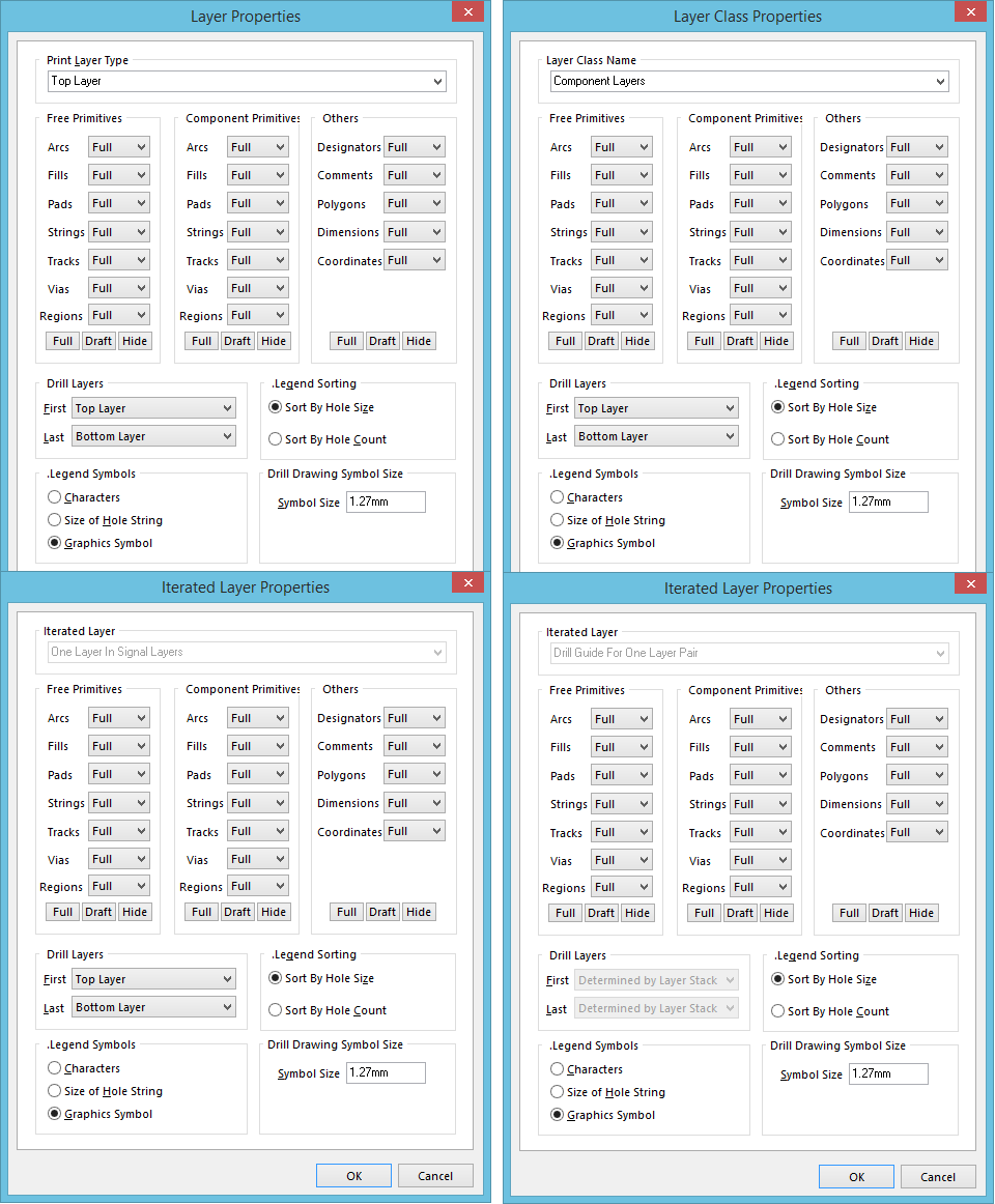
The various incarnations of the Layer Source Properties dialog.
Summary
This dialog allows the designer to configure the properties of a newly-added, or existing, layer entity. This could be a standard layer, a layer class, or an iterated layer (created automatically when adding a new printout set, or drill printout set).
Access
The dialog is accessed in the following ways:
- From the PCB Printout Properties dialog, by:
- Double-clicking on the entry for an existing layer entity.
- Selecting an existing layer entity, right-clicking, and choosing the Properties command from the context menu.
- From the Printout Properties dialog, by:
- Double-clicking on the required layer entity in the Layers region.
- Selecting the required layer entity in the Layers region, and clicking the Edit button.
Options/Controls
Top Region
The control presented in this region of the dialog differs, depending on the layer entity being configured:
- Standard Layer - when configuring a standard layer, this region presents the Print Layer Type field. Use it to choose/change the required layer. The drop-down presents all layers defined for the board.
- Layer Class - when configuring a layer class, this region presents the Layer Class Name field. Use it to choose/change the required layer class. The drop-down presents all existing layer classes defined for the board (as reflected in the Object Class Explorer dialog).
- Iterated Layer (associated with a printout set) - when configuring the iterated layer associated with a printout set, this region presents the Iterated Layer field. This is a read-only field that simply states One Layer In <LayerClass>, where <LayerClass> is the specific layer class chosen for the parent printout set.
- Iterated Layer (associated with a drill printout set) - when configuring the iterated layer associated with a drill printout set, this region presents the Iterated Layer field. This is a read-only field that simply states <DrillLayer> For One Layer Pair, where <DrillLayer> is the specific drill layer (Drill Drawing or Drill Guide) chosen for the parent drill printout set.
Free Primitives
This region of the dialog provides controls to determine how the free primitives on a layer are displayed on the printout. For the following free primitive objects, use the associated drop-down field in each case to choose whether to display the object fully (Full), in outline mode only (Draft), or hide the object (Off).
- Arcs
- Fills
- Pads
- Strings
- Tracks
- Vias
- Regions
The following buttons are available at the bottom of the region, to quickly switch the setting for all objects in a single action:
- Full - click this button to set the display option for all free primitives to Full.
- Draft - click this button to set the display option for all free primitives to Draft.
- Hide - click this button to set the display option for all free primitives to Off.
Component Primitives
This region of the dialog provides controls to determine how the component primitives on a layer are displayed on the printout. For the following component primitive objects, use the associated drop-down field in each case to choose whether to display the object fully (Full), in outline mode only (Draft), or hide the object (Off).
- Arcs
- Fills
- Pads
- Strings
- Tracks
- Vias
- Regions
The following buttons are available at the bottom of the region, to quickly switch the setting for all objects in a single action:
- Full - click this button to set the display option for all component primitives to Full.
- Draft - click this button to set the display option for all component primitives to Draft.
- Hide - click this button to set the display option for all component primitives to Off.
Others
This region of the dialog provides controls to determine how other objects on a layer are displayed on the printout. For the following objects, use the associated drop-down field in each case to choose whether to display the object fully (Full), in outline mode only (Draft), or hide the object (Off).
- Designators
- Comments
- Polygons
- Dimensions
- Coordinates
The following buttons are available at the bottom of the region, to quickly switch the setting for all objects in a single action:
- Full - click this button to set the display option for all objects to Full.
- Draft - click this button to set the display option for all objects to Draft.
- Hide - click this button to set the display option for all objects to Off.
Drill Layers
Use this region of the dialog when configuring a drill layer (Drill Drawing/Drill Guide).
- First - use this field to specify the starting layer for the required drill pair. The drop-down will list all available signal and internal plane layers defined in the board's layer stack.
- Last - use this field to specify the finishing layer for the required drill pair. The drop-down will list all available signal and internal plane layers defined in the board's layer stack.
.Legend Symbols
Use this region of the dialog to specify the type of symbols to be used in the printed drill drawing legend. Choose from either Characters, Size of Hole String, or Graphics Symbol.
.Legend Sorting
Use this region of the dialog to specify the property by which information in a printed drill drawing legend is to be sorted. Choose to either Sort By Hole Size, or Sort By Hole Count.
Drill Drawing Symbol Size
Use this region of the dialog to define the size of symbols when printing the Drill Drawing Layer. Enter the required value in the region's Symbol Size field.