
Variant Options
Other Related Resources
Parent page: WorkspaceManager Dialogs
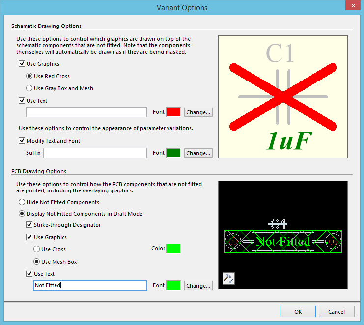
The Variant Options dialog.
Summary
This dialog allows the designer to configure the way in which varied components are presented on the schematic sheets (which then flows through to printed or PDF'd outputs), and in PCB drawing type outputs, such as assembly drawings.
Access
The dialog is accessed by clicking the Drawing Style button, at the bottom of the Variant Management dialog.
Options/Controls
Schematic Drawing Options
- Use Graphics - enable this option if you wish to have graphics displayed over schematic components that are not fitted while the documents are being printed. Choose one of the following options:
- Use Red Cross - use this option to overlay non-fitted components with a red cross.
- Use Gray Box and Mesh - use this option to overlay non-fitted components with a gray mesh box.
- Use Text - enable this option to display a string of characters over the not-fitted logical component.
- Text Box - use this field to specify the text that will be overlayed on non-fitted components.
- Font - click the color swatch to access the Choose Color dialog, with which to change the color of the overlay text. Click the Change button to access a standard font dialog from where to change the appearance of the overlay text.
- Modify Text and Font- enable this option to modify the appearance of varied parameters, both in the compiled document view of the schematic, and in schematic prints.
- Suffix - use this field to specify a suffix that will be added to all varied parameters.
- Font - click the color swatch to access the Choose Color dialog, with which to change the color of the text displayed in relation to varied parameters. Click the Change button to access a standard font dialog from where to change the appearance of the text.
PCB Drawing Options
- Hide Not Fitted Components - enable this option to have not-fitted components excluded on generated assembly drawings.
- Display Not Fitted Components in Draft Mode- use this option to enable the display of non-fitted components in assembly drawings, in draft mode. Any combination of the following options can be enabled and configured:
- Strike-through Designator - use this option to display the designator for a non-fitted component with a strike-through.
- Use Graphics - enable this option to apply a graphical overlay for non-fitted components in assembly drawings. Choose one of the following options:
- Use Cross - use this option to overlay non-fitted components with a cross.
- Use Mesh Box - Use this option to overlay non-fitted components with a mesh box.
- Color - click the color swatch to access the Choose Color dialog, with which to change the color of the overlay cross/mesh box.
- Use Text - enable this option to apply a textual overlay for non-fitted components, in assembly drawings.
- Text Box - use this field to specify the text that will be overlayed on non-fitted components.
- Font - click the color swatch to access the Choose Color dialog, with which to change the color of the overlay text. Click the Change button to access a standard font dialog from where to change the appearance of the text.