Project Options - Default Prints
Contents
Parent page: WorkspaceManager Dialogs
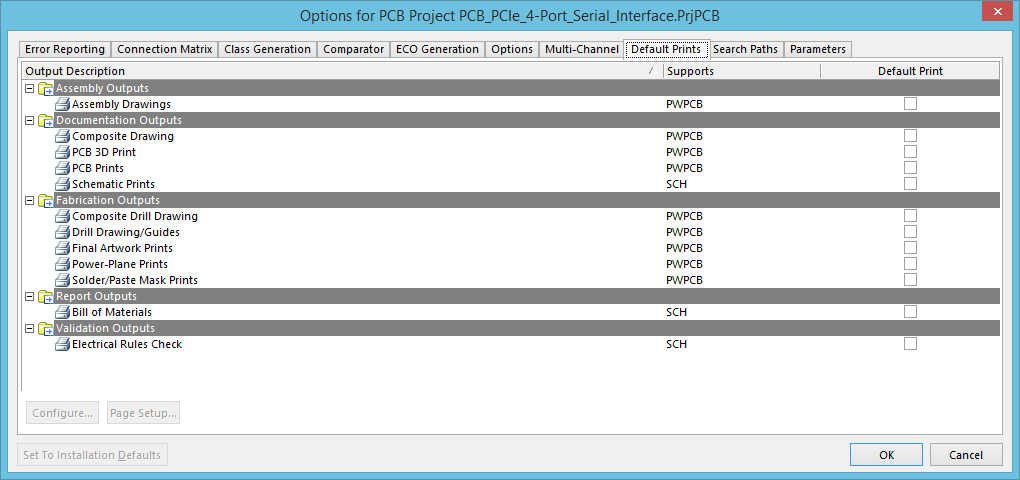
The Default Prints tab of the Options for PCB Project dialog.
Summary
This tab of the Options for PCB Project dialog enables you to set up the default print outputs for the Schematic and PCB editors. It is these nominated defaults that are used when running the following commands from the editors' main menus:
- Outputs | Documentation |
 .
.
- Outputs | Documentation | » Print Preview.
Access
This is one of multiple tabs available when configuring the options for a project – accessed from within the Options for PCB Project dialog. This dialog is accessed by:
- Clicking Project | Content | , from the main menus in the Schematic Editor, or the PCB Editor.
- Right-clicking on the entry for the project itself, on the Projects panel, and choosing Project Options from the context menu.
Options/Controls
The main area of the tab presents a listing of all supported print-based outputs that can be generated from the schematic and PCB editors. Output types are grouped into the following categories:
- Assembly Outputs - this category offers the following print output types: Assembly Drawings.
- Documentation Outputs - this category offers the following print output types: Composite Drawing, PCB 3D Print, PCB Prints, Schematic Prints.
- Fabrication Outputs - this category offers the following print output types: Composite Drill Drawing, Drill Drawing/Guides, Final Artwork Prints, Power-Plane Prints, Solder/Paste Mask Prints.
- Report Outputs - this category offers the following print output types: Bill of Materials.
- Validation Outputs - this category offers the following print output types: Electrical Rules Check.
For each entry, the following information is displayed:
- Output Description - what is given by using this print output type.
- Supports - the editor for which this print output type is supported. This will either be schematic (SCH), or PCB (PWPCB).
- Default Print - indicates whether this print output type is to be used as the default print type (enabled), or not (disabled).
Below the list, the following buttons are available:
- Configure - click this button to access an associated dialog with which to configure the currently selected print output. The dialogs involved are:
- PCB Printout Properties dialog - for configuring Assembly Drawings, Composite Drawing, PCB Prints, Composite Drill Drawing, Drill Drawing/Guides, Final Artwork Prints, Power Plane Prints, and Solder/Paste Mask Prints.
- PCB 3D Print Settings dialog - for configuring PCB 3D Prints.
- Schematic Print Properties dialog - for configuring Schematic Prints.
- Bill of Materials dialog - for configuring a Bill of Materials report.
- Electrical Rules Check Setup dialog - for configuring an Electrical Rules Check validation report.
- Page Setup - click this button to access a page setup dialog for the currently selected print output, with which to configure how the software outputs the specified printout to the chosen printer, in terms of paper, scaling, and color settings. From within this dialog, you can access the relevant configuration dialog, the printer setup dialog, preview the printout, and ultimately print the output, sending it to the nominated printing device.