
Printout Properties
Other Related Resources
Parent page: WorkspaceManager Dialogs
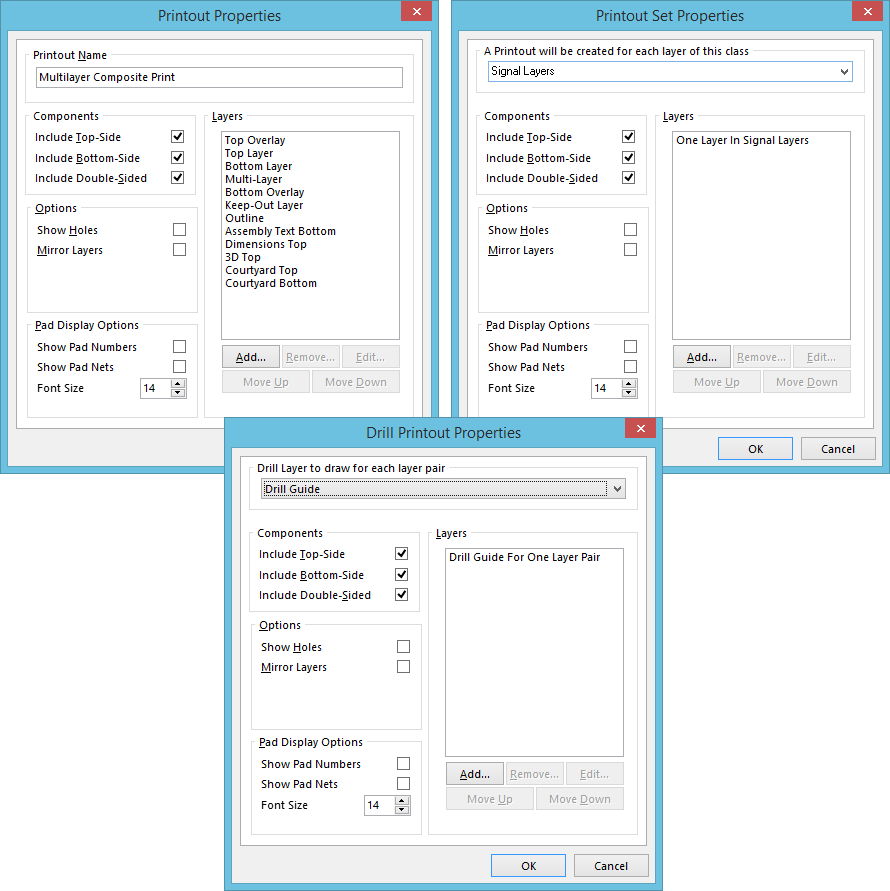
The various incarnations of the Printout Properties dialog.
Summary
This dialog allows the designer to configure the properties of a newly-added, or existing, printout/printout set.
Access
The dialog is accessed from the PCB Printout Properties dialog in the following ways:
- Double-clicking on the icon to the left of a printout's/printout set's name.
- Selecting a printout/printout set, right-clicking, and choosing the Properties command from the context menu.
Options/Controls
Top region
The control presented in this region of the dialog differs, depending on the printout entity being configured:
- Standard Printout - when configuring a standard printout, this region presents the Printout Name field. Use it to change the name for the printout as required, giving a more meaningful name that will readily identify its nature and purpose.
- Printout Set - when configuring a printout set, this region presents a control for specifying the layer class to be used. A separate printout will be created for each layer in the nominated layer class. Use the field's drop-down to choose from a list of all existing layer classes defined for the board (as reflected in the Object Class Explorer dialog).
- Drill Printout Set - when configuring a drill printout set, this region presents a control for specifying which drill layer to draw for each distinct layer pair (drill pair). Choose from either Drill Guide, or Drill Drawing.
Components
- Include Top-Side - enable this option to include all components on the top side of the board (those whose Layer property is set to Top Layer).
- Include Bottom-Side - enable this option to include all components on the bottom side of the board (those whose Layer property is set to Bottom Layer).
- Include Double-Sided - enable this option to include all components that include both top and bottom layer pads, such as PCB Edge Connectors.
Options
- Show Holes - enable this option to include pad and via holes on the printout.
- Mirror Layers - enable this option to mirror the layers included in the printout.
Pad Display Options
- Show Pad Numbers - enable this option to show pad numbers on the printout.
- Show Pad Nets - enable this option to show pad net information on the printout.
- Font Size - use this control to determine the size of the font used for pad number and net text.
Layers
This region is the 'heart' of printout configuration, providing the necessary controls to add, edit, and order, the layers that are to make up the printout.
- Layer List - a list of the layers currently included on the printout (or each printout in a printout set). The layer at the bottom of the list will be drawn first in the printer's memory when the image is rendered. Each layer above is then rendered, in turn, on top. Select a layer and use the Move Up and Move Down buttons to change its position in the render order.
- Add - click this button to add another layer to the printout (or each printout in a printout set). The Layer Properties dialog will appear, from where you can choose from a list of all used layers for the board, and with which to configure the properties for the chosen layer as required.
- Remove - click this button to remove the selected layer entity(ies) from the list.
- Edit - click this button to edit the currently selected layer entity in the list. The relevant incarnation of the Layer Source Properties dialog will appear (Layer Properties/Layer Class Properties/Iterated Layer Properties), with which to configure the properties for the entity as required.
- Move Up - click this button to move the currently selected layer entity(ies) upward in the list, thereby changing the print rendering order.
- Move Down - click this button to move the currently selected layer entity(ies) downward in the list, thereby changing the print rendering order.