3D Body
Contents
Parent page: PCB Objects

A sphere, a cylinder and 4 extruded rectangles have been used to create the 3D body for an LED.
Summary
A 3D body is a primitive polygonal design object that is used to represent the 3 dimensional shape of the physical component that is mounted on the assembled PCB. Any number of 3D body objects can be used together to create complex shapes. The available 3D body shapes include extruded polygon, cylinder and sphere. They can be placed into a PCB library component footprint. Their overall shape is displayed when the editor is switched to 3D display mode (press the 3 shortcut). 3D body objects can be placed on any mechanical layer.
Availability
3D bodies are available for placement in the PCB and PCB Library Editors, by clicking Home | Place | ![]() from the main menus.
from the main menus.
Placement
After launching the command the 3D Body dialog will open. Placement is made by performing the following sequence of actions:
- In the 3D Body dialog select the 3D Model Type from the available shapes: Extruded, Cylinder or Sphere. Alternatively, enable the Generic STEP Model option, should you wish to embed an external STEP model.
- Each 3D body can be named, this helps identify each element when multiple 3D bodies are placed to create a complex shape. Enter a suitable name in the Identifier field.
- Each shape must have a defined size before it can be placed. If the chosen shape is Extruded then define the Height, if it is Cylinder define the Radius and Height, if it is Sphere define the Radius.
- Set the 3D Color and the 3D Color Opacity as required. Note that these can be edited later if needed.
- Click OK to close the dialog and return to the workspace.
- If the shape is Cylinder or Sphere, the cursor will be moving in the workspace with a rectangular shape attached. Click to place the 3D body.
- If the shape is Extruded the cursor will present, ready to define the the polygonal base shape of the extruded 3D body:
- Click to define the first vertex.
- Move the cursor ready to place the second vertex. The default behavior is to place 2 edges with each click, with a user-defined corner shape between them. Refer to the Placement Modes section.
- Continue to move the mouse and click to place further vertices.
- After placing the final vertex, right-click or press Esc to close and complete placement of the 3D body. There is no need to manually close the 3D body as the software will automatically complete the shape by connecting the start point to the final point placed.
- The 3D Body dialog will re-appear, ready to configure the next 3D Body for placement. Configure the dialog settings and continue placing 3D bodies, or click Cancel to exit placement mode.
Placement Modes
While placing an extruded 3D body there are 5 available corner modes, 4 of which also have corner direction sub-modes. During placement:
- Press Shift+Spacebar to cycle through the 5 available corner modes: 45 degree, 45 degree with arc, 90 degree, 90 degree with arc, and Any Angle.
- Press Spacebar to toggle between the two corner direction sub-modes.
- When in either of the arc corner modes, hold the or keys to shrink or grow the arc. Hold the Shift key as you press to accelerate arc resizing.
- Press the 1 shortcut key to toggle between placing 2 edges per click, or one edge per click. In this second mode the dashed edge is referred to as the look-ahead segment (as shown in the last image in the set below).
- Press the Backspace key to remove the last vertex.
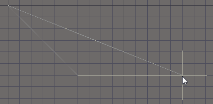
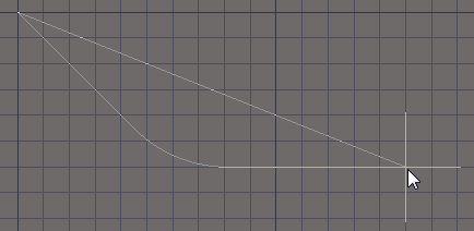
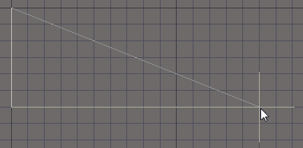
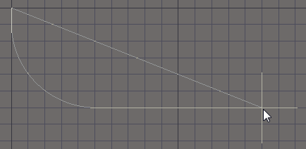
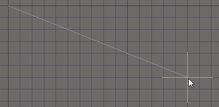
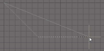
Press Shift+Spacebar to cycle through the 5 available corner modes, press the 1 shortcut to toggle placement between 2
edges or 1 edge.
Graphical Editing
This method of editing allows you to select a placed 3D body object directly in the workspace and change its size, shape, or location, graphically.
For an extruded 3D body, click once on the object to select it, which puts it into edit mode. The outer shape of the 3D body object is defined by a series of edges: where each edge is represented by an end vertex at each end, and a center vertex in the middle, shown as a solid white squares. Each end vertex represents the location where 2 edges meet.
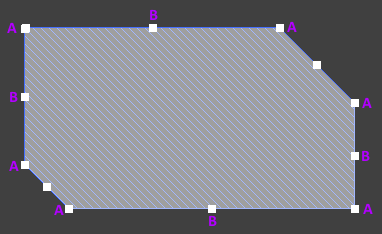
A selected extruded 3D body.
- Click and drag A to move the applicable end vertex.
- Click and drag B to move the applicable center vertex, effectively creating a new end vertex, and splitting the original edge into two.
- Click anywhere along an edge, away from editing handles, and drag to slide that edge.
- Ctrl+click anywhere along an edge, away from editing handles, to insert a new end vertex.
- To remove an end vertex, click and hold on the vertex, then press the Delete key.
- Click anywhere on the 3D body – away from editing handles – and drag to reposition it. While dragging, the 3D body can be rotated or mirrored:
- Press the Spacebar to rotate the 3D body anti-clockwise or Shift+Spacebar for clockwise rotation. The Rotation Step size is defined on the PCB Editor – General page of the Preferences dialog.
- Press the X or Y keys to mirror the 3D body along the X-axis or Y-axis respectively.
Non-Graphical Editing
The following methods of non-graphical editing are available:
Via an Associated Properties Dialog
Dialog page: 3D Body
This method of editing uses the following dialog to modify the properties of a 3D body object.
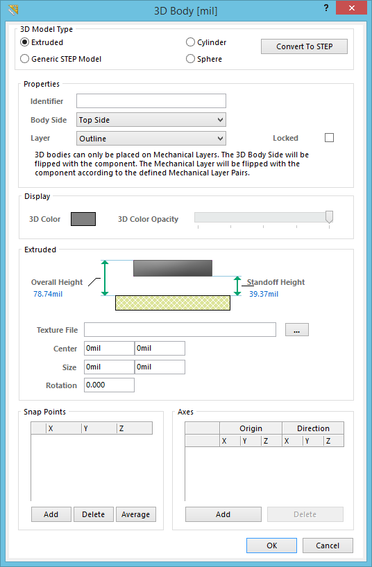
The 3D Body dialog.
The 3D Body dialog can be accessed during placement by pressing the Tab key.
After placement, the dialog can be accessed in one of the following ways:
- Double-clicking on the placed 3D body object.
- Placing the cursor over the 3D body object, right-clicking and choosing Properties from the context menu.
Via an Inspector Panel
Panel pages: PCB Inspector, PCBLIB Inspector
An Inspector panel enables the designer to interrogate and edit the properties of one or more design objects in the active document. Used in conjunction with appropriate filtering, the panel can be used to make changes to multiple objects of the same kind, from one convenient location. The Inspector panel is ideal for editing 3D body objects as the changes can be seen in the workspace without needing to close a dialog. For example, if you are aligning two body objects with the display in 3D mode, you can watch as you change the Model Z setting for one of the objects (there is a brief pause after changing a 3D Body setting in the Inspector panel).
Other 3D Body Editing Features
Including a Texture
Extruded objects can also include an image overlaid on the upper most surface. When a Texture File is added it is automatically stretched to fit to cover the entire upper surface of the 3D body, as shown in the image below. This can be adjust by altering the Center location, Size and Rotation settings in the 3D Body dialog. Note that the texture file is embedded in the Library or Board file.
Supported Texture File formats include: *.bmp;*.dds;*.dib;*.hdr;*.jpg;*.pfm;*.png;*.ppm;*.tga.
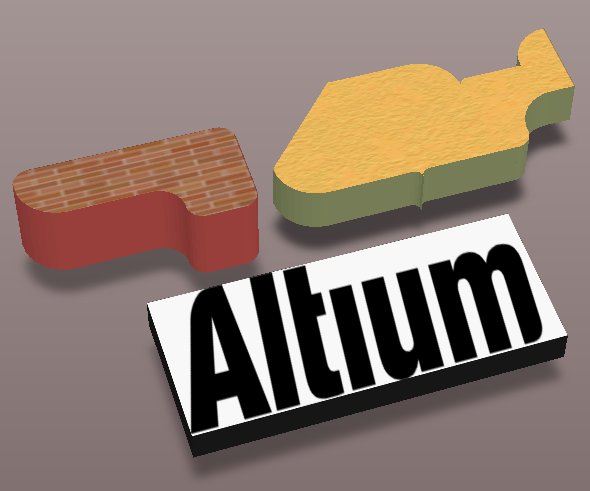
A texture or logo can be added to an extruded 3D Body object.
Snap Points and Axes
Snap points and lines of Axis can be added to a 3D body. Snap points define points at which the 3D body can be held. When the cursor is moved close to a snap point and a click and hold is performed, the cursor will jump to and hold the 3D body at the snap point. The image below shows a 3D body with 2 snap points defined. Axes can be added to provide a visual aid for positioning and orienting a 3D body.
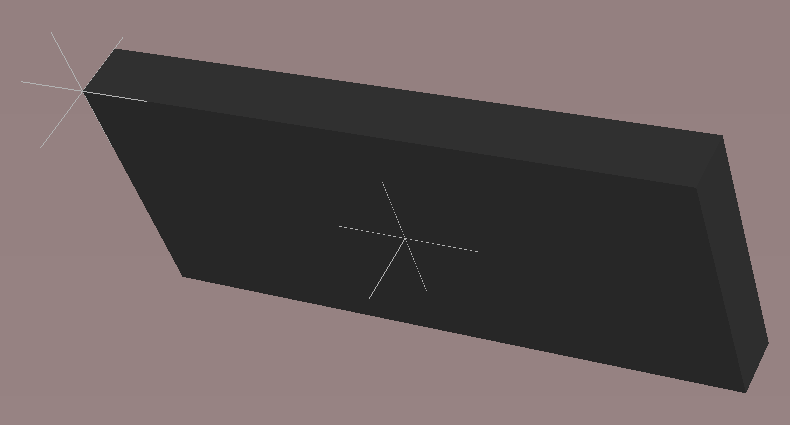
Add Snap Points to a 3D Body to hold the object during positioning.
Maintaining Component Clearances
Add Component Clearance design rules to check for collisions between components that include 3D body objects in the X, Y and Z planes. This allows the designer to fit one component over another component. Multiple rules can be defined to handle different clearance requirements. Note that the Design Rule Check does not test for 3D body objects passing through the board.