
Wire
Contents
Parent page: Schematic Objects
Wires are used to create electrical connectivity in a schematic.
Summary
A wire is a polyline electrical design primitive that is used to form electrical connections between points on a schematic. It is analogous to a physical wire.
Availability
Wires are only available for placement in the Schematic Editor, by clicking Home | Circuit Elements | ![]() from the main menus.
from the main menus.
Placement
After launching the command, the cursor will change to a cross-hair and you will enter wire placement mode. Placement is made by performing the following sequence of actions:
- Click or press Enter to anchor the starting point for the wire.
- Position the cursor and click or press Enter to anchor a series of vertex points that define the shape of the wire.
- After placing the final vertex point, right-click or press Esc to complete placement of the wire.
- Continue placing further wire objects, or right-click or press Esc to exit placement mode.
- Use the Backspace or Delete keys to remove the last wire segment placed.
Placement Modes
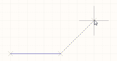
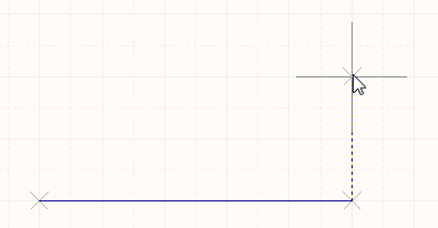
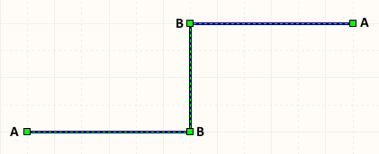
When placing a wire there are 3 placement modes, 2 of which have Start and End sub-modes. The mode specifies how corners are created when placing wires and the angles at which wires can be placed. During placement:
- Press Shift+Spacebar to cycle through the 90 Degree, 45 Degree and Any Angle modes.
- While in the 90 Degree or 45 Degree mode (known as true orthogonal modes), press Spacebar to cycle between the Start and End sub-modes.
- During placement, the current placement mode is displayed in the Status bar. You can change modes at any time during wire placement.
- In modes other than Any Angle, the line segment attached to the cursor is a look ahead segment. The segment you are actually placing precedes this look ahead segment.
 45 degree mode
 90 degree mode
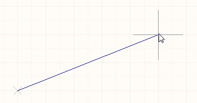 Any angle mode
Press Shift+Spacebar to cycle through the different placement modes.
Guided Wiring
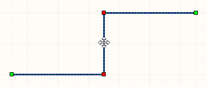
Schematics have a definable electrical grid that makes it easy to define electrical connections between objects. As you are placing a wire, when the wall falls within the electrical grid range of another electrical object the cursor will snap to the fixed object and a Hot Spot (red cross) will appear.
Hot Spot (red cross).
The Hot Spot guides you to where a valid connection can be made and automatically snaps the cursor to electrical connection points.
The electrical grid can be defined on the Sheet Options tab of the Document Options dialog (Project | Content | ![]() ). It is recommended that you set the electrical grid to be slightly smaller than the current snap grid, or it becomes difficult to position electrical objects one snap grid apart.
). It is recommended that you set the electrical grid to be slightly smaller than the current snap grid, or it becomes difficult to position electrical objects one snap grid apart.
Graphical Editing
This method of editing allows you to select a placed wire object directly in the workspace and change its size and/or shape, graphically.
When a wire object is selected, the following editing handles are available:
Selected Wire, ready for graphical editing.
- Click and drag A to reposition the end points of the wire.
- Click and drag B to move a wire vertex. The end points will remain anchored.
- Ctrl+click and drag on a wire segment to grab that segment and reposition it. The end points and other vertices will remain anchored.
- Right-click on a vertex point and choose the Edit Wire Vertex n command to access the Vertices tab of the Wire dialog, with the entry for the
nthvertex selected ready for editing. - Ctrl+click and hold on a wire segment, then press Insert on the keyboard to add a vertex at that point.
- Click and hold on a vertex, then press Delete on the keyboard to remove that vertex.
With the wire selected, click on a segment to individually select that segment. This wire 'sub-selection' is distinguished by the associated editing handles becoming red in color.
Individual segment sub-selection.
The associated vertices for the segment can then be edited directly using the SCH Inspector panel, with any changes appearing immediately on the schematic.
Non-Graphical Editing
The following methods of non-graphical editing are available:
Via an Associated Properties Dialog
Dialog page: Wire
This method of editing uses the Wire dialog to modify the properties of a Wire object.
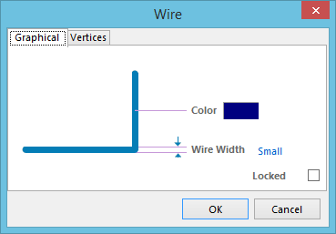
The Wire dialog.
The dialog can be accessed during placement by pressing the Tab key.
After placement, the dialog can be accessed in one of the following ways:
- Double-clicking on the placed Wire object.
- Placing the cursor over the Wire object, right-clicking and choosing Properties from the context menu.
Via the SCH Inspector Panel
Panel page: SCH Inspector
The SCH Inspector panel enables the designer to interrogate and edit the properties of one or more design objects in the active document. Used in conjunction with the Find Similar Objects dialog, the panel can be used to make changes to multiple objects of the same kind, from one convenient location.
Autojunctions
A T-junction in a wire is automatically connected by a junction (Compiler-Generated Juntion). If the Break Wires At Autojunctions option is enabled, on the Schematic - General page of the Preferences dialog, an existing wire segment will be broken into two at the point where an autojunction is inserted. For example, when making a T-Junction, the perpendicular wire segment will be broken into two segments, one each side of the junction. With this option disabled, the wire segment will remain unbroken at the junction.